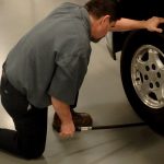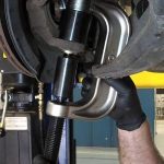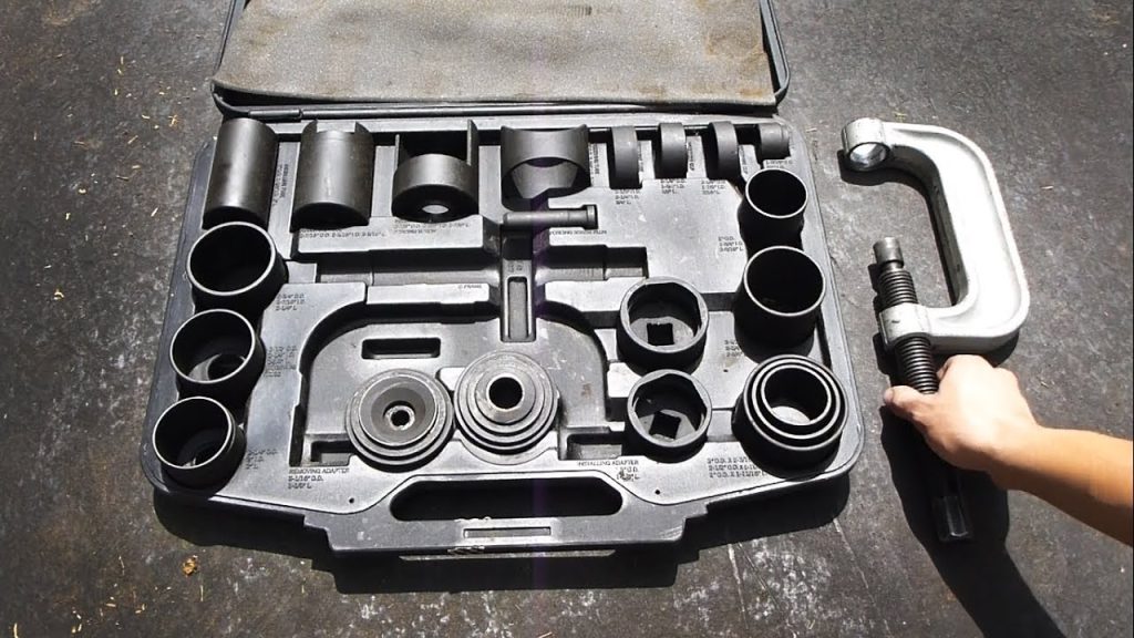

Press a ball joint into its receiving component only with a supported installation procedure and the correct press adapters. The setup must drive the intended housing surface, support the receiving part appropriately and keep the joint aligned with its bore. It must also leave clearance for the stud, boot and any features that are not designed to carry pressing force. A joint entering the hole is not enough; it must reach the specified position without damage and accept its required retention. This guide focuses on the press-in housing operation.
Separating a stud from a knuckle is a different job, and a bolted or integral joint should not be treated as a press-in design. Confirm the exact vehicle and replacement part before setting up equipment. If the receiving bore is damaged or the correct adapters are unavailable, stop. A larger press does not make an uncertain fit or unsupported tool stack acceptable.
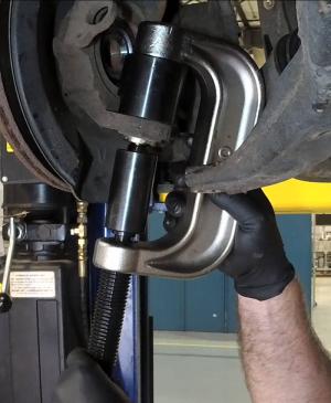
Credit: www.delphiautoparts.com
Confirm that pressing is the supported installation method
Check the parts catalogue and installation instructions for the exact joint position and suspension configuration. Determine whether the joint is separately replaceable and whether it enters from a specified side. Identify the shoulder, retaining-ring groove or other feature that defines its installed position. Do not assume the old part's removal direction can simply be reversed without reading the new part's requirements. Replacement designs can have preparation or orientation details that were not apparent during disassembly. Inspect the receiving component before installation.
A bore that is damaged, distorted or too loose cannot be repaired by tightening the stud nut afterward. Follow the applicable inspection and replacement criteria. Do not grind the bore until the new joint becomes easy to insert, and do not add adhesive or substitute an oversize joint without a supported application-specific instruction. The fit is part of the designed connection, not a difficulty to remove from the job. Clean and prepare only as directed.
Remove contamination without changing the dimensions or damaging required surfaces. Tool instructions and part instructions may address different aspects of preparation; resolve their application to the actual job before proceeding. Do not copy a lubrication recommendation from one vehicle onto another. The press screw's maintenance lubricant, the housing's installation condition and grease inside the joint are separate matters. A product suitable for one location is not automatically suitable for the others.
Build a complete adapter and support arrangement
- The forcing side must contact the surface the joint manufacturer permits to carry installation load. It should not press through the moving stud, a protective boot or an unsupported cover merely because those areas are accessible. The opposite support must carry the receiving component without bending it and provide enough clearance for the joint's travel. Identify both sides of the load path before applying pressure: where force enters, where it passes and where the structure reacts it. OTC’s 7248/7249 instructions show a dedicated installation adapter and receiving tube and emphasize final alignment checks.
- Those drawings belong to the described tool and applicable configurations. They are not approval to reproduce a similar-looking stack with random sockets. An adapter's opening, depth and support edge all matter. A cup that fits over the stud may still bottom against the housing or fail to support the intended area.
Check tool coverage and condition before loading it
- Confirm that the press and adapter combination covers the application. A kit advertised for many vehicles may still require an additional adapter for yours. Check the tool manufacturer's instructions for compatible components and permitted operation. Inspect the forcing screw, frame, contact faces and other load-bearing parts. Do not use visibly damaged or deformed tooling.
- A worn thread or unstable cup creates a problem that additional force cannot solve. The vehicle or removed component also needs secure support independent of the press. On-vehicle access may be allowed for some installations and unsuitable for others. If the service procedure calls for bench work, do not assume a larger clamp makes on-car installation equivalent. Keep clear of the loaded setup and use the prescribed protective equipment.
Do not position hands between adapters to steady them while pressure is being applied. Avoid homemade substitutes whose load capacity and geometry are unknown. A general C-clamp is not automatically a ball-joint press, and a socket's normal use as a fastener tool does not establish that it is an approved press cup. Heating, freezing or impact operation should not be introduced as universal aids. Use only methods supported by the exact part, receiving component and tool instructions.
Set orientation and initial alignment deliberately
Check for alignment marks, tags, offset features or grease-fitting restrictions before the housing starts entering the bore. MOOG’s elliptical-joint guidance explains that certain joints have a directional opening and require a defined orientation. Incorrect rotation can limit intended movement even if the housing is fully seated. Do not assume a round exterior means orientation is irrelevant.
Once the joint is pressed home, correcting it may require additional removal and a new serviceability decision. Place the joint squarely according to the instructions and inspect the setup from more than one useful angle. Verify that the driver and receiver remain concentric with the intended motion. Confirm that a shoulder or casting feature is not holding a cup at an angle.
Check clearance at the far side before travel begins. If access prevents you from seeing the relevant contact, improve the access through the supported procedure rather than relying on feel. Delphi’s Honda Civic press-in example demonstrates adapter placement and protection of the stud during a specific installation.
Its value is the attention to clearance and alignment, not a promise that the same adapters suit other cars. Read the applicable diagram for your assembly. A tool that can be made to fit is different from a tool arrangement documented to apply force at the right surfaces.
Recognize normal progress and reasons to stop
- Watch the housing's entry and the tool's seating as the operation progresses under the tool instructions. There is no universal pressing force or number of screw turns that proves correct installation. If the joint begins to tilt, a cup shifts or the receiving component deforms, stop. Do not keep pressing in the hope that the housing will straighten itself. Release the tool safely before making any adjustment, and assess whether the attempted installation has damaged the fit. An abrupt change in resistance can have several explanations, including reaching a specified seat or an unintended obstruction. Identify which occurred rather than assuming that a harder turn means the joint is finished. Check the manufacturer's seating reference and the available travel. A cup bottoming against the joint can feel like a completed installation while the housing remains short of its required position. The visible and specified acceptance criteria must agree.
Keep the boot and moving mechanism out of the load path
- Some boots are supplied already installed; others have a specified later fitting operation. MOOG’s boot-installation guidance illustrates that separate boot fitting requires its own instructions. Do not remove a preinstalled boot casually to make an unsuitable adapter fit. Do not squeeze a boot between the receiver and component or use it to locate the press stack. A torn or displaced boot may compromise protection even when the new joint initially feels smooth. Protect the stud threads and any sealing surfaces throughout handling. Keep dirt and metal fragments away from the moving bearing area. If a grease fitting is supplied separately, follow the installation sequence and orientation requirements. Do not use the fitting as a support or grip point. The joint's lubrication service is not a way to compensate for damage caused during pressing, and a sealed joint should not be punctured to add grease.
Verify seating and retention before releasing the job
- Check the housing position against the part instructions. Confirm that any required retaining ring is the correct item and is seated as specified. A ring that will not engage should trigger a seating, fitment or groove inspection, not immediate grinding of the groove or substitution of a thinner ring. Retention is not optional simply because the press fit felt tight. Likewise, an apparently seated ring does not prove an incorrect housing orientation is acceptable. Inspect the surrounding component for damage caused during installation. Confirm that no tooling contacted an unintended area and that the boot remains sound. Unload and remove the press only as directed by its operating instructions. Do not leave a vehicle or component with stored tool pressure while arranging additional parts. If a defect is found, document it and obtain a supported correction rather than concealing it during the next assembly stage.
Complete the remaining assembly as a separate operation
- Pressing the housing home does not secure the stud connection or finish the repair. Install the stud into its specified receiving component with the correct hardware, torque sequence and locking arrangement.
Restore any associated brake, wiring or steering components disturbed for access. Complete required lubrication, alignment assessment and functional checks.
Our installation acceptance guide covers those remaining verification questions. If the joint was pressed in at a workshop but the surrounding assembly will be completed elsewhere, record the part number, orientation and seating checks performed.
Identify any receiving-component concern. Do not describe the entire suspension repair as complete when only the press operation was done.
Clear records help the next technician understand which fasteners and checks still remain. A successful press operation preserves the receiving component, installs the correct joint in the required position and leaves the protective and retention features intact.
It is judged by those outcomes rather than the strength of the press or the difficulty of the last turn. If the fit, tooling or acceptance criteria remain uncertain, stop before the vehicle returns to service.


Automotive reference information. Confirm specifications in the manual for your exact vehicle. Original replacement guides link to their research sources. About us