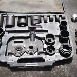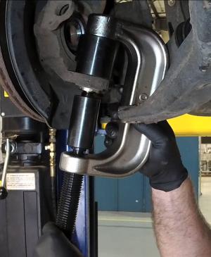

A ball joint is correctly installed only when its fit, position, retention, fastening and protection meet the requirements for that application. Being able to bolt the suspension back together is not enough. A housing can be incompletely seated, a boot can be trapped or the wrong nut can reach an apparent stopping point while the connection remains unsuitable. Treat installation as a sequence of acceptance checks, not simply the reverse of removing the old part. Use the vehicle and replacement-part instructions together.
They determine the housing position, orientation, fastener specifications and any follow-up work. This guide focuses on checking the result after fitting begins; it does not supply universal torque values or a single pressing method for every joint. For the housing operation itself, see press-in adapter and alignment checks. Keep a partly assembled or uncertain suspension out of use until all required checks have passed.
Verify fit and retention before final tightening
Confirm the identity of the replacement before accepting its fit. Check the catalogue position, vehicle qualifiers and supplied instructions against the actual assembly. A part that enters the mounting hole is not necessarily correct for the application. If aftermarket arms or knuckles are fitted, establish the compatible joint and procedure for that combination. Do not assume the original vehicle catalogue covers every modified component. Retain packaging and part identification until the repair has been verified. Inspect the receiving component under the applicable criteria. A damaged taper or loose housing bore can make a new joint insecure. MOOG’s stud-fit bulletin emphasizes the receiving connection and the consequences of an unsuitable fit. Tightening a nut cannot restore the shape of a worn hole. If damage is found, stop and determine whether the knuckle, arm or another component requires replacement. Do not make an uncertain fit appear secure with extra washers, adhesive or additional torque.
For a press-in housing, check its specified seating reference rather than assuming that resistance at the press means completion. Verify that the shoulder or other defined feature is positioned as instructed and that the receiving component was not distorted. An adapter may have reached an obstruction before the joint reached its seat. If a retaining-ring groove is inaccessible or a ring will not fit, investigate the cause. Do not alter the groove to compensate for an incorrectly seated or incorrect part. For bolted, threaded or integral assemblies, apply that design's acceptance criteria instead. A press-fit rule should not be transferred to a flanged joint simply because both occupy the same position on different vehicles. Identify which surfaces locate the part and which fasteners retain it. Check that any mounting flange is seated as specified and that no debris or misplaced hardware prevents proper contact. A partially tightened flange can conceal a gap until final inspection becomes difficult. Confirm orientation independently from seating depth.
MOOG’s elliptical-joint guidance describes designs where the opening must face the intended direction to permit the required motion. A fully seated housing can still be incorrectly rotated. Check alignment marks, tags or grease-fitting restrictions before access is lost. Do not rotate an installed press-fit housing with improvised force to correct a missed instruction. Obtain the supported correction and assess whether the attempted installation remains serviceable. Verify all separate retainers. These may include a specified ring, flange hardware or another feature defined by the assembly. Use the correct new items where required. A retaining ring should not be accepted merely because part of it appears to enter its groove. Inspect the full accessible engagement as directed. Retainers and housing fit work together; one is not permission to disregard the other.
If the drawing shows an item that is absent, resolve that before moving to the stud connection. Check supplied fasteners against the instructions. MOOG’s replacement-hardware guidance explains that nut geometry can be important, particularly where the receiving component incorporates an insert. Do not transfer old hardware solely because it looks familiar or uses a convenient socket. A different flange or locking style may be intentional. If the kit contains an unexpected arrangement, confirm the application and instructions with the supplier rather than improvising a combination of old and new parts. Inspect the stud threads and receiving connection before tightening. The nut should start in the manner specified without unexplained binding or cross-threading. If the stud spins, follow the approved counterholding or seating method. Do not grip a protected surface with locking pliers or use a high-speed impact burst to conceal the problem. Our spinning-stud guide distinguishes that installation issue from damaged threads and incorrect taper fit.
Use the actual tightening procedure for each fastener. Identify the units, preparation condition, stages and any angle requirement. Distinguish the stud nut from housing bolts, pinch bolts and other disturbed suspension connections. A value for one is not a general ball-joint specification. Apply the prescribed measured method with suitable equipment. If access requires an adapter, account for its effect according to the tool arrangement rather than treating an awkward hand estimate as equivalent. Complete the locking system exactly as instructed. A self-locking nut and a castellated nut with a cotter pin are different arrangements. Use required replacement hardware and follow the specific alignment rule. Do not loosen a nut arbitrarily to fit a pin, and do not treat a fitted pin as evidence that the clamping procedure was correct. If the locking feature lies in an unexpected position, recheck the hardware and fit before declaring the connection finished.
Check protection, surrounding systems and return to service
Inspect the dust boot after all tooling has been removed. Check for cuts, twists, trapped edges and displacement according to the part instructions. MOOG’s dust-boot guidance addresses products whose boots need a separate fitting operation, demonstrating why the sequence should not be assumed. A new joint with a damaged boot is not an acceptable finished repair merely because it moves smoothly now. Resolve the damage before it is hidden by the wheel or other components.
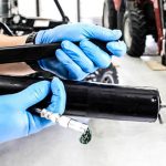
Follow the lubrication requirements for the exact part. Some joints are sealed, while others require specified grease service. Do not puncture a sealed boot or add a fitting that the part does not support. Do not assume that more grease will compensate for a pinched boot or damaged bearing. If a grease fitting has an orientation requirement, confirm access and clearance without using it as a handle to twist the installed housing.
Restore the associated components disturbed for access. Check brake-hose routing and support, sensor-wire clips, steering connections, shields and any driveshaft-related work against the procedure. A hose should not be twisted or stretched because the knuckle was moved during assembly. Do not leave wiring near moving or hot parts. If a hydraulic brake connection was opened, complete its separate bleeding and leak checks.
That requirement is not cancelled by the ball joint itself being correctly fitted. Verify any fasteners whose final tightening depends on a specified suspension position. Follow the procedure for the individual connection rather than applying a universal rule that everything must be tightened with the wheel hanging or everything must be tightened under vehicle weight. The support arrangement must remain safe while the required position is established. If the instructions cannot be fulfilled with the available equipment, have the remaining work completed professionally before use.
Complete the prescribed stationary inspection before road testing. Confirm secure wheel installation and fastening. Check that the required movement and clearance are present and that no unresolved looseness, damaged boot or omitted retainer remains. A test drive is not an appropriate way to decide whether a questionable suspension connection is secure. Keep the vehicle out of service if any installation criterion remains unexplained.
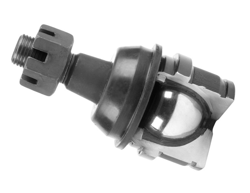
Credit: www.autozone.com
Determine the alignment work required by the service procedure and the components disturbed. Delphi’s service guidance places ball-joint work within the broader suspension repair. Do not infer that a car is aligned because the steering wheel appears centred or the replacement part matches the old number. Arrange the required measurement and correction. If the vehicle is not safe to drive to the facility, organize suitable transport rather than relying on a temporary assembly.
Once the initial checks pass, carry out the specified controlled functional verification. Reassess the original complaint and watch for new steering resistance, unusual noises or warnings. Stop if abnormal behavior occurs. A quieter first journey is not a substitute for correct fit and torque, and persistent noise should lead to diagnosis rather than additional tightening of the new joint. Other suspension components may have contributed to the original symptoms.
Record the installed part, receiving-component condition, hardware renewed and checks completed. Include alignment results and any application-specific follow-up instructions. If one workshop pressed the joint and another completed the assembly, make clear which operation each performed. A statement that the joint was installed should not conceal that final torque or alignment remains pending. Clear documentation is useful when reviewing a later complaint or warranty concern.
There is no need to invent a universal retightening interval for all ball joints. Follow the instructions for the particular repair and continue the vehicle's prescribed inspections. If a fastener repeatedly loosens or movement returns, investigate the cause rather than adding another maintenance turn. The installation is accepted when the specified fit, retention, fastening and operational checks agree. That is a more reliable standard than judging the job by how difficult the last nut was to turn.


Automotive reference information. Confirm specifications in the manual for your exact vehicle. Original replacement guides link to their research sources. About us