Test a fuel pump driver module by following the vehicle’s diagnostic sequence for its power supply, ground, control or communication and pump output. A code naming the fuel-pump circuit is a starting point, not a verdict against the module. The pump and wiring must be considered too.
This is a framework for evaluating the diagnosis. Exact connectors, signals and pass/fail values belong to the service information for your vehicle. Do not apply battery power to a terminal because an online diagram for a different model labels it as an output.

Credit: www.f150forum.com
Confirm the vehicle uses the suspected component
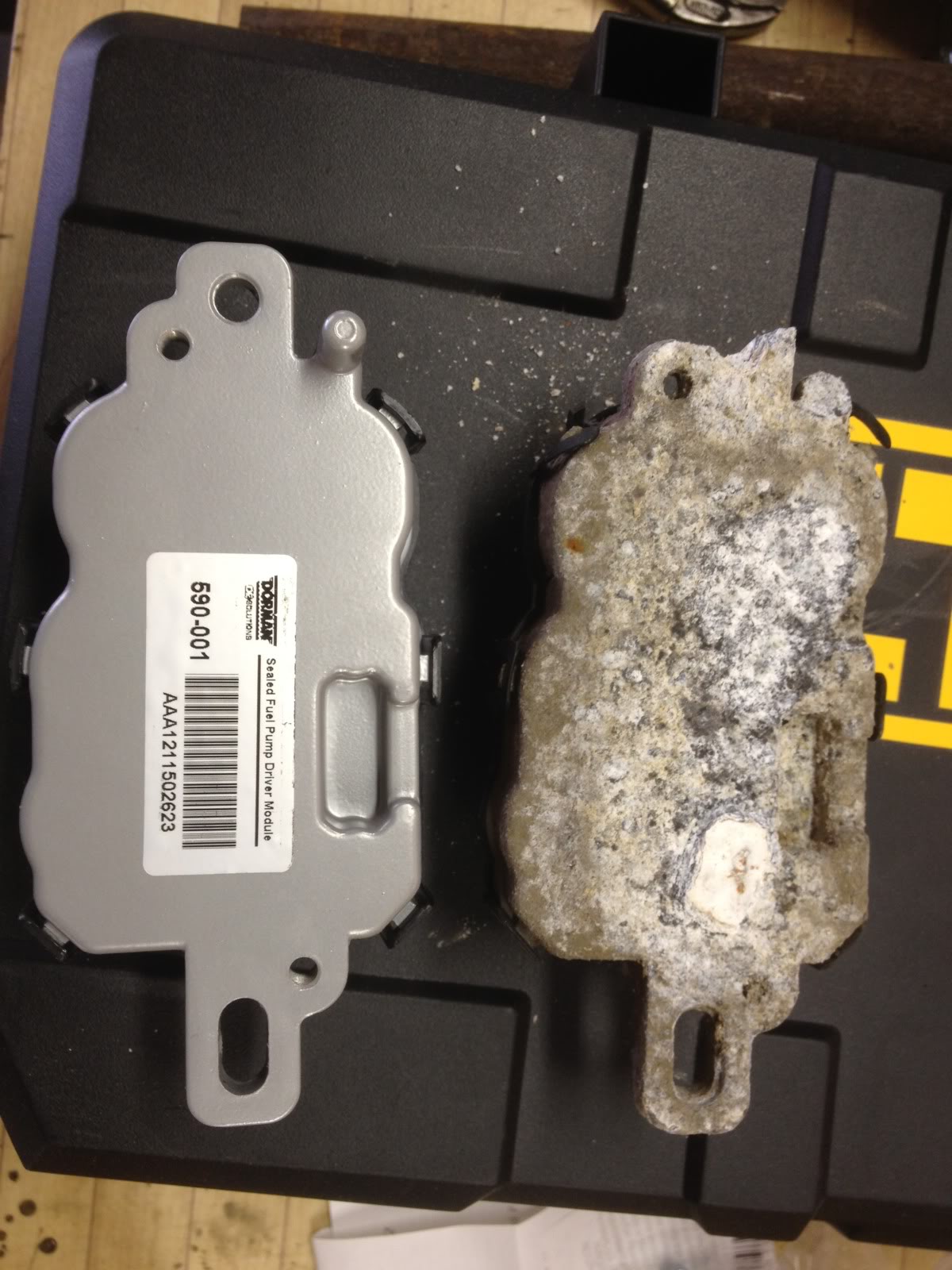
Identify the module by the correct diagram and part information. Names vary, and a fuel-system complaint does not establish that the car has a separate driver in the location shown in another vehicle’s tutorial. Record the engine and module number.
Check the repair history. A recently changed pump, disturbed connector or aftermarket wiring can alter the diagnostic starting point. Include these details when seeking professional testing rather than reporting only the fault code.
Credit: www.f150forum.com
Save codes and the conditions of failure
Record current and stored codes before clearing them. Note whether the complaint is a no-start, an intermittent stall or a delivery problem while running. Keep any available fault-event data. Clearing everything at the beginning can remove useful context.
Ford’s 2024 OBD operation summary documents distinct fuel-system control and monitoring faults for its covered systems. That illustrates why different circuit faults must not all be translated into “replace the driver.” It is not a universal code-to-component chart.
Inspect without substituting appearance for testing
Credit: www.f150forum.com
Look for damaged wiring, unsecured connectors and visible deterioration using the safe access procedure. Document what you find. A visibly damaged connection deserves correction, but a clean-looking module is not proof that its circuits work.
Do not disconnect components with the system operating unless the service procedure calls for it. Avoid probing methods that spread terminals or damage seals. Creating an intermittent connector fault during diagnosis can make the original complaint harder to isolate.
Verify supply and ground in the required condition
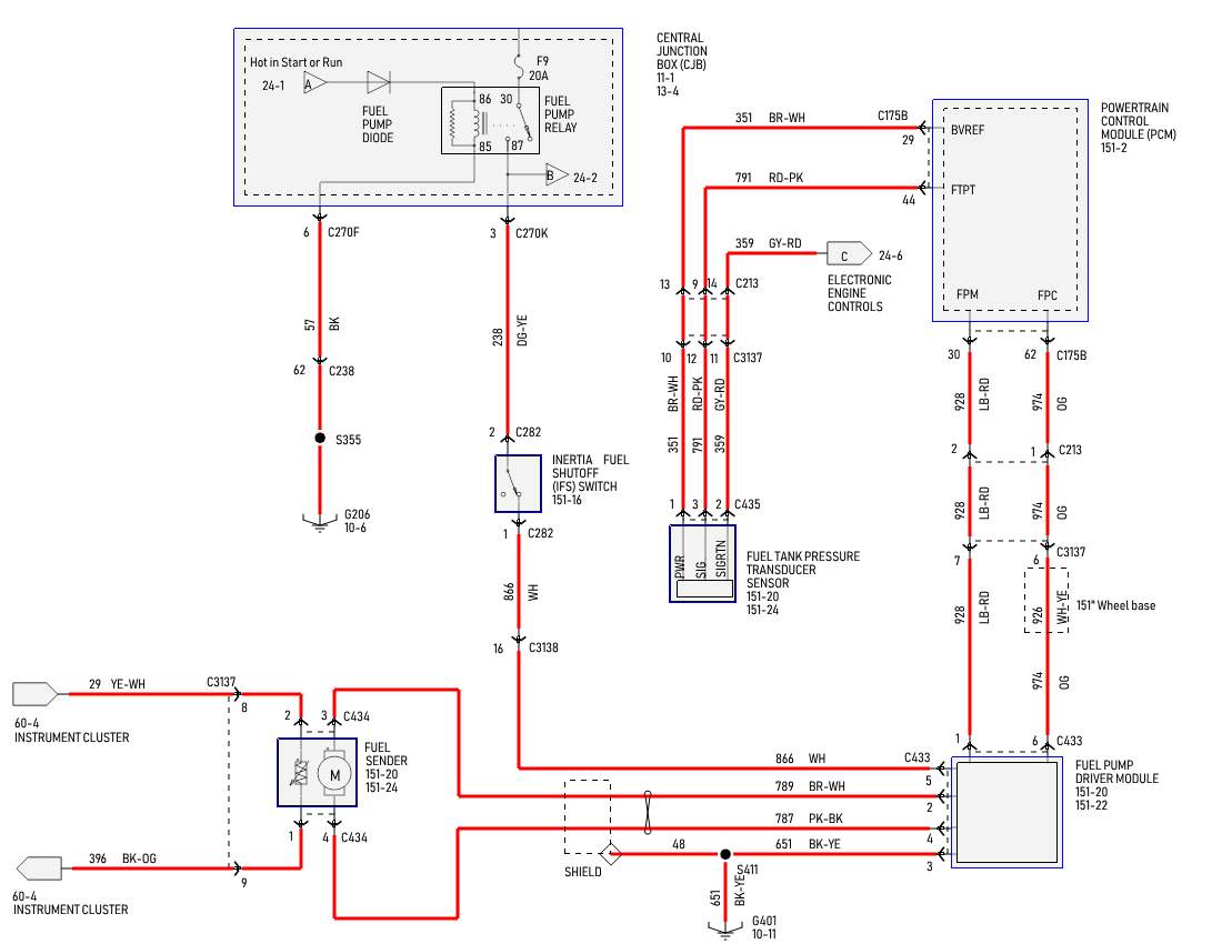
Check the prescribed electrical supply and return path under the conditions stated in the diagnostic procedure. An unloaded voltage reading alone may not answer whether the circuit performs when the system operates. Use the specified test method and equipment.
Delphi’s voltage-drop guidance supports checking supply losses before blaming a pump. The same diagnostic discipline matters when tracing the circuit around a driver: establish where the electrical problem actually occurs instead of assuming the control box caused it.
Establish whether a valid command reaches the module
The controller must be receiving the operating conditions and signals its design requires. Follow the diagnostic checks for command or communication faults. If the vehicle is not asking for pump operation, a lack of output may be a consequence rather than proof of a defective driver.
A scan-tool command is useful only if the tool supports the operation and the prerequisites are met. Note whether the test was accepted. Do not interpret a refused or unsupported active test as a failed module.
Evaluate output together with the pump circuit
Use the manufacturer’s output-test method. Controlled pump circuits are not all equivalent to a simple steady battery supply, so an ordinary meter reading can be misleading without context. Do not use a generic resistance value or waveform from another system as the pass/fail standard.
Investigate the pump circuit as the procedure directs before condemning the module. Bypassing the driver and hearing the pump run does not demonstrate correct operation under control or prove that a permanent bypass is safe.
Require a conclusion that accounts for the whole circuit
A defensible replacement decision explains which tests passed, which failed and why the failure points to the module rather than its inputs or load. Ask for that record before authorizing parts. Resolve damaged wiring and related faults as part of the repair.
If replacement is justified, check whether programming or setup is required. Complete final verification under the original complaint conditions where safely possible; deleting the code is not the final test.


Automotive reference information. Confirm specifications in the manual for your exact vehicle. Original replacement guides link to their research sources. About us