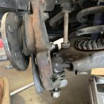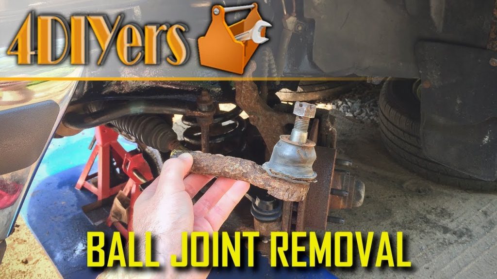

Before removing a ball joint, confirm that the vehicle is safely supported, suspension loads are controlled, the exact connection is identified and its retention has been accounted for. Also confirm that the required tool can reach the correct surfaces and that the replacement can be installed afterward. These checks prevent a partly dismantled vehicle becoming an improvised experiment with spring forces, damaged threads or unsupported components.
This is a removal-readiness checklist, not a universal upper- or lower-joint procedure. The same description can cover several suspension layouts and attachment designs. Use the vehicle's service information and the replacement manufacturer's instructions for the actual sequence.
If a joint is already loose or damaged, keep the vehicle out of use until it has been assessed. Do not drive on an unfinished connection just because the nut has been started again.
Confirm the exact assembly before scheduling removal
Record the model year, vehicle model, drivetrain and relevant suspension option. Identify the affected side and joint position. Check whether the replacement is a separate joint or a complete arm assembly. Photograph the installed configuration and compare it with the service diagram, especially if aftermarket suspension parts are present. A diagram for a nearby model year may show a different retention arrangement.
Decide whether removal is for replacement of the joint or access to another component. If the joint is intended for reuse, the permitted separation method and boot protection become especially important. Do not assume that a method acceptable for scrapping an old joint preserves it. Define which parts must remain serviceable before choosing a tool. Our connection-identification guide explains the distinction between stud separation and housing removal.
Verify the information needed before the first fastener moves
- Have the complete removal and installation instructions available. Check for specified replacement fasteners.
- Confirm the direction of housing removal where pressing is involved. Identify any orientation marks that must be recorded before the old joint comes out.
- Check whether the procedure requires removing the arm or knuckle for bench work. Confirm the final tightening and locking instructions as well as the disassembly steps.
- Delphi’s press-in joint example is explicitly tied to a Honda Civic application. It demonstrates why the whole sequence must be understood, but it does not supply a universal sequence for other cars.
- If your procedure depends on a special adapter or a support point not shown clearly, resolve that before starting.
A paused planning stage is safer and easier to manage than a paused job after the suspension connection has been released.
Understand the support and stored-load requirements
An upper joint is not automatically unloaded, and a lower joint is not serviced identically on every suspension. The design determines how forces reach the connection. Use the specified vehicle restraint, lifting points and support arrangement. Never rely on a hydraulic jack as the only support. Do not release a ball joint to discover whether a spring or arm moves afterward.
If spring-load control is required, use the prescribed equipment and method. An ordinary jack under a convenient arm surface is not an adequate substitute for missing instructions. Ensure that any auxiliary support cannot lift the vehicle off its main stands unexpectedly. Keep people clear of potential component movement. If you cannot describe what supports each part after separation, the removal is not ready to begin.
Check the tool as a complete system
- Inspect the press or separator and its instructions before fitting it. Confirm the tool's application coverage and compatible adapters.
- Check that threads, contact surfaces and retaining features are serviceable. Verify the space available for the tool's full operating travel.
- Do not assume a kit contains the correct adapter because its label mentions trucks or imports. Confirm the actual combination for the application.
- OTC’s operating instructions require tooling and component alignment checks before pressure is applied. That requirement includes the entire stack, not just the forcing screw.
- A receiver must permit the moving part to enter without bottoming against it. A driver must contact the intended surface without crushing a boot or loading the stud incorrectly.
- Do not substitute damaged sockets, loose scrap spacers or an unrated clamp for a documented adapter arrangement.
Account for access, routing and controlled movement
- Trace the brake hose before moving the knuckle. Identify the wheel-speed sensor lead and its retaining clips.
- Check the steering linkage for restrictions on movement. Identify any driveshaft clearance or articulation limits relevant to the procedure.
- Determine how the knuckle will be supported after release. Do not let any line or cable become its suspension strap.
- Note the original routing before removing clips. If a brake caliper must move for access, support it independently.
- Do not open a hydraulic connection merely because the hose makes the work awkward unless the service procedure requires it. Opening the circuit adds bleeding and leak-check requirements.
- Keep friction components protected from chemicals used elsewhere in the job.
- Remove only the parts needed for the specified access.
- Unnecessary disassembly creates more connections to verify later.
- Check that the tool can operate without contacting a sensor, boot or thin edge.
Visibility matters: being able to turn a screw is not the same as being able to confirm correct seating.
If access is inadequate, follow the supported alternative, such as bench work where specified, rather than assembling the tool by feel and hoping its cups stayed aligned.
Do not replace missing equipment with a force shortcut
- A request to remove a joint without the correct tool usually means the plan needs to change. A hammer, homemade press stack or heated knuckle is not a universal substitute for an application-approved separator or press.
- The surrounding component may have material or construction limits that an online demonstration does not address. Do not infer suitability from the fact that the old joint is being discarded.
- The receiving arm or knuckle may still need to survive unchanged. Damaging it can increase the repair scope and create an unsafe fit for the replacement.
- Our separator guide helps assess tool compatibility. If the appropriate tool is unavailable, arrange rental, workshop assistance or another supported service option before dismantling further.
Identify every retention feature
Locate the stud nut, pinch bolt or other specified stud retainer. Identify the housing retention separately.
- Look for a retaining ring where the design uses one. Check for a flange, shoulder or other feature that determines direction.
- Do not assume that removing the visible nut frees every part of the joint. Clean only enough, using suitable methods, to identify the construction reliably.
- An unfamiliar sleeve or insert requires investigation. MOOG’s insert guidance describes specific designs where an insert may remain attached to a removed stud.
- That is a reason to inspect the assembly, not a universal instruction to pry a ring away. If the parts diagram does not match what you see, pause.
A retained structural component can look like corrosion until its function is understood.
Check replacement readiness before extracting the housing
Compare the new part identification and installation information before the old housing is removed. Confirm that supplied retainers and hardware match the instructions. Check whether boot fitting occurs before or after pressing. MOOG’s elliptical-joint guidance shows that some designs require a defined rotational orientation. Record the required reference while the surrounding assembly is still easy to identify.
Have an inspection plan for the receiving bore or taper. A new part may be unsuitable for a damaged opening even if its catalogue application is correct. If removal exposes distortion, cracking or an insecure fit, the job must pause for a supported repair decision. Do not enlarge the opening, add adhesive or select an oversize part without application-specific authorization from the relevant service information.
Use clear stop conditions during the operation
- Stop if the tool shifts. Stop if the housing begins to tilt.
- Stop if the receiver runs out of travel. Stop if the supporting component distorts.
- Stop if unexpected wiring or hose tension appears. Do not reach into a loaded tool stack to realign it.
- Release force safely under the tool instructions before reassessing. Keep clear of the possible release path.
- Do not add a longer handle as the first response to unexplained resistance.
- Check the removal direction again.
- Recheck the retention features.
- Recheck the support surfaces and adapter identities.
- If the setup is correct but the joint remains immovable, use the supported escalation route.
- That may require different tooling, bench access or replacing a damaged surrounding part.
- Our stuck-joint guide focuses on that decision.
The important distinction is between controlled resistance and evidence that the operation is no longer following its intended path.
Leave the next stage safe and traceable
- After removal, keep parts organized. Identify any component that was damaged or already defective. Protect exposed openings from debris.
- Inspect the receiving surfaces before fitting the new joint. Do not hide suspect marks with aggressive cleaning.
- Confirm that the replacement instructions still apply to the condition found. Update the repair scope if another component fails inspection.
If the job cannot continue immediately, secure the vehicle and detached parts in a suitable work area. Do not leave the knuckle hanging or a tool under load.
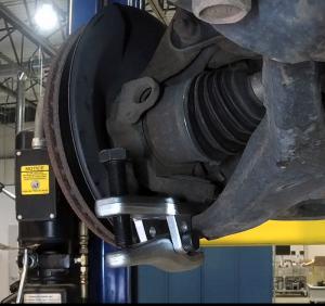
Credit: www.delphiautoparts.com
Arrange parts or recovery without reusing a known unsafe connection as a temporary transport solution. Keep notes on where the work stopped and why.
A second technician should be able to understand the condition without guessing which fasteners were tightened. Removal readiness is complete only when support, access, retention, tooling and the next installation stage are understood together.
The checklist is not intended to make every repair suitable for home work. It makes the decision explicit: proceed with a verified procedure and equipment, or stop before an uncertain connection is released.


Automotive reference information. Confirm specifications in the manual for your exact vehicle. Original replacement guides link to their research sources. About us