
Changing a ball joint involves more than exchanging the visibly worn part. A complete repair confirms the diagnosis, identifies the correct replacement unit, controls suspension loads, removes the specified connections, checks the receiving components, installs and secures the new part, then completes the required verification. The precise order and tools depend on the vehicle and joint design. There is no reliable universal sequence based only on whether the joint is called upper or lower. Use this guide to plan the work and understand a workshop estimate.
Obtain the exact service procedure before dismantling, including torque values, one-time-use hardware and support requirements. If the vehicle has a confirmed loose or damaged suspension connection, do not continue driving while gathering parts. Arrange suitable recovery where needed. A replacement plan should make the vehicle safe at the end, rather than leave alignment, locking hardware or inspection as tasks for another day.
The first practical question is whether the joint is separately replaceable on this application. Some installations accept a replacement joint, while others are serviced as a complete arm or another assembly. Match the parts catalogue to the actual vehicle and existing hardware, particularly if the suspension has been modified. Buying a loose joint before confirming the supported repair can create a job that the available procedure and equipment cannot safely finish.
Build the job around clear stages and completion criteria
Start with a documented diagnosis. A clunk, steering complaint or uneven tyre wear can come from more than a ball joint. Delphi’s ball-joint service guidance explains the relationship between joint condition and handling symptoms, but those symptoms still require inspection. Ask which interface has abnormal movement and whether the inspection used the correct suspension-loading condition. Internal socket wear, a loose stud connection and a loose housing fit should not be treated as the same defect. Each may change the parts that must be replaced. Identify the vehicle by model year, exact model, drivetrain and relevant suspension configuration. Check the required position and catalogue qualifiers. Compare the replacement instructions with any existing aftermarket arms or knuckles. A part that fits another trim or axle option is not confirmed by a similar photograph. Record the selected part number and the procedure used to identify it. That record is useful if the replacement's hardware or orientation differs from the removed assembly. List the complete materials needed before starting. These can include the joint or arm, specified new nuts or bolts, retainers, boots and approved lubricant where applicable. MOOG’s fastener guidance explains why supplied hardware can differ for functional reasons.
- Do not automatically transfer the old nut because its socket is already on the bench. Conversely, do not install an extra washer merely because one was included in a different kit. Resolve the intended hardware arrangement against the actual instructions. Check tool and access requirements as a separate stage. Separating a stud from a knuckle and pressing a housing from an arm are different operations. A general press kit may lack the adapters needed for the application. Verify that tooling can be positioned without loading the boot, bending the receiving part or obstructing the moving housing. If the procedure calls for bench work, suitable support or a particular separator, plan that capability before the vehicle is immobilized. Our removal-interface guide helps distinguish these operations. Read the safety setup in the service information. Vehicle restraint, lifting points, stand placement and control of spring or suspension forces are part of the repair. Do not substitute a jack under an arbitrary arm for an instructed load-control method. Identify how the knuckle will be supported after the stud releases. Brake hoses, wiring and driveshaft joints must not become its support.
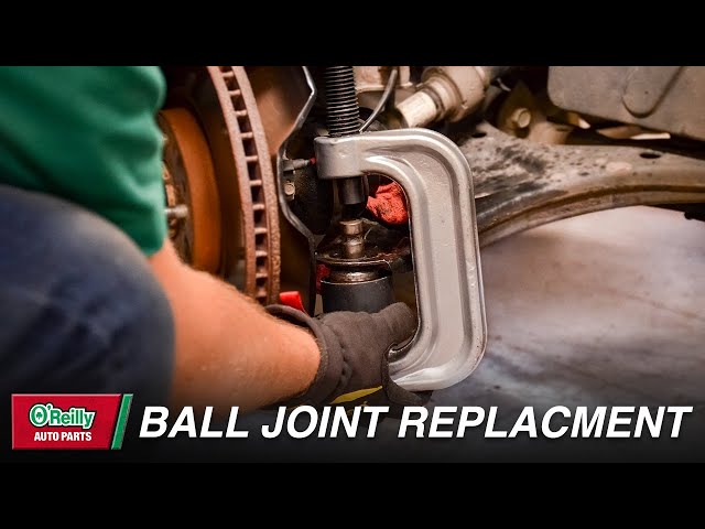
- If the necessary equipment or experience is missing, a professional installation is a practical change in plan, not a reason to improvise a release method. Carry out only the disassembly needed by the applicable procedure. Document cable and hose routing before moving parts. Keep removed hardware separated by location so that similar-looking bolts are not interchanged. If a brake caliper must move for access, support it independently and protect the hydraulic hose. If the hydraulic circuit is opened, account for bleeding and leak checks later. A ball-joint replacement does not automatically require opening that circuit, and unnecessary disassembly adds avoidable dependencies. During removal, watch for unexpected movement or damage. A tool slipping, a housing tilting or an insert remaining on the stud requires reassessment. Do not respond by increasing force before identifying what happened. Delphi’s Honda Civic replacement example demonstrates a complete application-specific sequence; it should be read as an example of planned stages rather than a generic recipe. The corresponding procedure for your vehicle governs direction, access and the condition of parts intended for reuse. Inspect the receiving component after the old joint is removed. A worn taper, damaged bore or distorted mounting area can make a new joint insecure.
- Installation should stop until the component meets its service criteria. Do not enlarge a hole to make a replacement easier to fit or add adhesive to rescue an uncertain interference fit without a supported procedure. The final estimate may legitimately change if dismantling exposes damage that was not visible beforehand. Ask for the finding that justifies that change. Prepare the replacement according to its own instructions. Confirm orientation, pressing contact surfaces, boot sequence and any retaining ring or flange arrangement. A joint that is symmetric from one viewpoint may have a directional opening or another alignment requirement. Protect the threads and sealing surfaces. Do not transfer a lubrication instruction from a different brand or design. The receiving fit and the moving bearing have different functions and may have different preparation requirements. Complete installation with the specified fasteners and tightening sequence. MOOG’s stud-torque bulletin emphasizes fit and a measured tightening procedure, rather than using force to compensate for a mismatch. Identify which specification applies to the stud nut, housing bolts and any other disturbed connections. Include required angle stages, loaded-position instructions and locking hardware where applicable.
A cotter pin is not a substitute for correct clamping. An impact setting is not proof of final torque. Protect and inspect the dust boot. MOOG’s boot-installation guidance covers products where the boot is not already installed, illustrating why its fitting sequence cannot be assumed. Confirm that it is seated, undamaged and not trapped by a tool or mating component. If the joint is greaseable, follow its specified initial lubrication procedure. If it is sealed, do not add a fitting or inject grease through the boot. More lubricant is not a repair for installation damage. Reassemble associated components and route lines and cables correctly. Restore any brackets, retainers and shields required by the vehicle. Complete wheel fastening and stationary checks before considering a road test. Confirm that all dismantled connections have been accounted for, rather than relying on an empty parts tray as evidence. Unexplained play, a damaged boot or a locking feature that cannot be installed correctly means the repair remains incomplete. Keep the vehicle out of service until that uncertainty is resolved.
Finish verification and document the repair decision
Determine the required alignment assessment from the service procedure and the components disturbed. Replacing or moving an arm, knuckle or related mounting can affect the work needed afterward. Do not promise that preserving a rough paint mark or installing the same part number eliminates every alignment requirement. Arrange the necessary measurement and correction as part of the repair plan. If the vehicle cannot safely be driven to an alignment facility, organize suitable transport rather than accepting an insecure temporary assembly. Perform the specified functional checks only after the stationary checks pass.
Verify the original complaint under controlled conditions appropriate to the repair. A quieter first drive is useful but does not establish that every fastening and fit is correct. If the symptom persists, return to diagnosis instead of tightening the new joint harder. If new steering resistance, warning messages or abnormal noises appear, stop and inspect the work and related components. Keep a concise record of the diagnosis, installed parts, receiving-component inspection, hardware renewed and verification completed. Include any alignment report and follow-up instructions associated with the specific parts.
This helps distinguish later wear from an unresolved installation issue. It also gives the owner a clear explanation of why the final job involved more than the price of the joint. A good record names the work actually performed without claiming that every possible future suspension fault has been eliminated. If the replacement is being performed away from home, agree in advance how an unexpected damaged arm or unavailable adapter will be handled. Keep the vehicle supported in a suitable work area while the plan changes. Do not reassemble a known defective connection solely to free a parking space.
Recovery, additional parts and access to the correct tools belong in the contingency plan. There is no universal mileage at which every ball joint should be changed. Condition, design, environment and service history affect the decision, and the vehicle's inspection requirements remain the starting point. Likewise, whether the opposite side needs replacement depends on its condition and applicable guidance. Inspect it rather than assuming either mandatory pair replacement or guaranteed serviceability. The complete repair is the one that addresses confirmed defects and leaves all affected connections ready for safe operation.

Credit: www.autozone.com


Automotive reference information. Confirm specifications in the manual for your exact vehicle. Original replacement guides link to their research sources. About us