
To get a ball joint out, first identify what is still attached. Separating the stud from a steering knuckle is different from removing the joint housing from a control arm. A press-in housing, bolted flange, threaded housing and integral arm assembly also require different approaches. The phrase ball-joint removal can describe any of these jobs, so choosing a tool before identifying the connection can send force through the wrong part.
Do not begin by hammering harder, heating the surrounding metal or borrowing whichever press looks large enough. Locate the vehicle-specific procedure and determine which parts must be supported, which retainers must be released and which components are intended to be reused. If a suspension connection is damaged or partly dismantled, keep the vehicle out of use. This guide helps define the job accurately; exact removal direction, support positions and tooling come from the applicable service information.

Credit: www.reddit.com
Separate the two main removal questions
The stud connects the moving joint to another suspension component. On a tapered connection, releasing that fit separates the attached components while leaving the joint housing installed. The housing itself may remain pressed into a control arm or knuckle. A stud separator therefore does not normally remove the complete press-in housing, and a housing press should not be arranged as though the stud were its driving surface. Name the interface before deciding which tool will act on it.
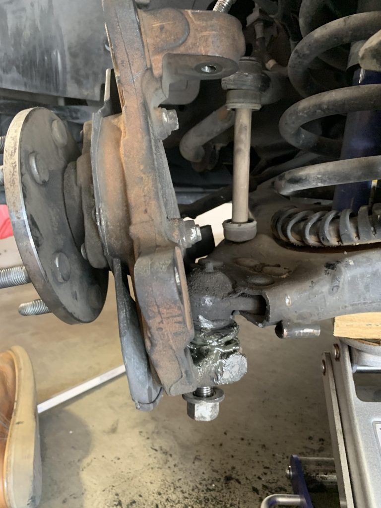
Look at the component diagram and the actual assembly together. Identify the stud, nut or other stud retainer, protective boot, housing edge and the part receiving the housing. Note which side the housing shoulder contacts and whether a ring or other retention feature is visible. Dirt can conceal those details, but aggressive cleaning can damage them. If the diagram and vehicle disagree, investigate whether a different brake or suspension option, aftermarket arm or previous repair explains the difference.
Delphi’s press-in joint example uses a specified Honda Civic application to illustrate separate stages of disassembly and pressing. It is useful evidence that the complete task contains distinct interfaces, not permission to copy its sequence onto every car. A reader looking only for the moment the joint pops loose can miss the preparation and support that made that moment controlled. Study the complete procedure before treating one photographed tool arrangement as a universal method.
Recognize how the housing is retained
- A press-in housing relies on its specified fit in the receiving part and may have a separate retaining ring. A bolted joint uses its designated flange and fasteners. Some original installations use rivets with a defined replacement procedure, while some joints are not separately serviceable from their arms. Threaded designs are another category. These descriptions are identification branches, not instructions to cut, press or unscrew anything that happens to resemble one of them.
- Confirm the supported replacement unit in the parts catalogue. If the manufacturer supplies the arm assembly for that application, do not assume the visible joint can be extracted and replaced independently. Conversely, an available replacement joint still needs the correct procedure and a sound receiving component. A part listing alone does not validate a worn bore. Record whether the intended repair replaces the joint, the arm, the knuckle or a combination, because that decision controls which surfaces must survive removal.
Inspect access and nearby parts before applying force
- Trace the brake hose, wheel-speed sensor wiring, steering linkage and, where present, the driveshaft around the connection. Identify which components must be disconnected or supported under the service instructions. A knuckle that suddenly becomes free can pull on those items if its movement has not been controlled. Never use a brake hose or sensor lead as a support strap. Avoid hanging a removed brake caliper by its hose while gaining tool access.
- Plan vehicle support independently from the removal tool. A press or separator is not a substitute for a lift or stands at approved points. Releasing a ball joint can change how spring or suspension loads are carried. The required support arrangement depends on the design, so a general instruction to jack under the lower arm is insufficient. If the procedure requires spring-load control or equipment not available, stop before the connection is released and arrange qualified assistance.
Choose a tool for the identified interface
- A separator needs the correct opening, reach and contact geometry for the stud connection. Its contact must not unintentionally load a boot, brake component or fragile edge. If reuse is planned, the chosen method must preserve the parts the service procedure requires to remain intact. A tool advertised as universal still has dimensional and operating limits. Our separator selection and use guide addresses that tool decision in more detail. A press-in housing instead needs the specified driving adapter, receiving space and support arrangement. OTC’s press instructions emphasize checking tooling and component alignment before applying pressure. The correct cup must allow the moving part to travel rather than trap it against the receiver. An ordinary socket that happens to fit around the housing is not automatically a safe press adapter. Both the tool's instructions and the vehicle procedure must support the setup.
Check for special construction rather than assuming corrosion
- An unexpected ring around the stud may be part of the receiving component, not material that should be driven away. MOOG’s knuckle-insert guidance describes applications where a separate insert can adhere to the stud during removal. That example matters because an apparently stuck joint can actually involve an additional component with its own replacement decision. Identify the construction before attempting to peel, cut or press an unfamiliar sleeve off the assembly. Similarly, a shoulder, retaining ring or joint orientation feature can explain why a housing will not move in the direction being attempted.
- Do not conclude that corrosion is the only obstacle because the tool is under load. Release stored tool pressure safely before inspecting the setup. If a retainer was overlooked, correct the preparation; if the direction is uncertain, return to the diagram. Heating or increasing leverage without resolving the uncertainty can destroy a component that was otherwise reusable.
Distinguish difficult removal from a damaged assembly
- A sound press fit or taper can resist release, but unusual movement deserves attention. If the housing tilts, a support cup moves, the receiving part distorts or the tool no longer sits squarely, stop. A higher force value would not explain why the setup changed. Do not extend a handle, add impact operation or strike a loaded tool unless the exact tool instructions permit that operation and the vehicle procedure supports it. There is no universal force threshold that makes every ball-joint setup safe.
- If the joint remains stuck after the identification and setup checks, move to a supported escalation plan. A workshop may need different application adapters, bench access or replacement of a damaged receiving component. That is a different decision from repeatedly trying the same misaligned stack. Our stuck-joint diagnosis guide separates a retained part, inaccessible interface and damaged fit from ordinary removal resistance.
Inspect the exposed connection before installation
- Removal provides access to surfaces that were hidden during the initial diagnosis. Inspect the housing bore or stud receiving surface under the applicable service criteria. A new ball joint cannot correct an out-of-round opening or damaged taper. MOOG’s stud-fit bulletin connects improper taper fit with a need to assess the receiving knuckle, not merely replace the joint.
Do not erase damage evidence by grinding or enlarging a hole until a new part enters. Keep the removed parts and retainers identified until the replacement is confirmed. Compare supplied hardware with the installation instructions rather than assuming every old washer should be transferred. A different nut or flange can be intentional.
Resolve a mismatch before pressing or tightening the replacement. If the new part requires an orientation mark, boot-installation sequence or particular retainer, have that information available before the first installation force is applied. The removal plan should also account for finishing the job. That includes the correct replacement parts, specified fasteners, torque procedure, protection of the boot and any alignment or system checks required by the disturbed components.
Opening a brake connection creates hydraulic work that is separate from ball-joint replacement. Disconnecting a sensor requires correct routing and reconnection. Do not leave those consequences until after the joint is out and the vehicle cannot be moved safely. If you are explaining the problem to a workshop, describe the stage reached: the stud remains in the knuckle, the stud is separated but the housing remains in the arm, or the housing is out and the bore needs assessment.
Include the vehicle identity, part numbers and any tool marks or unusual movement. Those facts are more useful than saying the ball joint is stuck. They allow the next person to plan the correct interface and protect the remaining serviceable parts. The right removal method begins with a precise description of the connection.
It ends with a receiving component that can be evaluated for safe installation, not merely a loose old joint. Treat identification, load control and inspection as part of getting the joint out. That approach avoids turning an ordinary replacement into unnecessary damage to the surrounding suspension.


Automotive reference information. Confirm specifications in the manual for your exact vehicle. Original replacement guides link to their research sources. About us