
If a ball joint will not come out, stop increasing force until you know which interface is stuck and why the setup is not progressing. A stud held in a taper, a housing retained in a bore, an overlooked ring and a tool that has run out of clearance can feel similarly immovable. They are not solved by the same action. The first escalation should be a better diagnosis of the stalled operation, not a longer handle or a hotter flame. Keep the vehicle securely supported and control any suspension load under the applicable service procedure.
Do not leave the tool loaded while reaching into the setup or changing its position. Do not drive a vehicle with a partly dismantled or uncertain suspension connection. If the job cannot be completed safely where it stands, arrange qualified help or suitable recovery. This guide addresses a removal that has stopped making progress; it does not prescribe universal striking points, heat levels or pressing forces. Before trying again, record what has already been done.
Note the tool used, the direction of attempted movement, which retainers were removed and whether any component shifted. Include damage to threads, boots or surrounding parts from earlier attempts. That information helps distinguish the original resistance from a new problem created during removal. It also gives a workshop a safer starting point than a description that simply says the joint is seized.
Identify what is actually resisting removal
Locate the boundary where movement is expected. If the stud remains in the knuckle but the housing is still correctly installed, the task is stud separation. If the stud is already free and the housing remains in an arm, it may be a housing-removal operation. If the housing itself is moving with the receiving component, the support or fit may be compromised. Our removal-interface guide helps name those stages before selecting another tool. Compare the assembly with the exact service diagram. Recheck the retention and removal direction. A concealed ring, shoulder, flange or other feature can block movement even when the visible nut is gone. Do not assume that rust is the explanation until the construction is understood. An aftermarket part or previous repair can also make the physical assembly differ from a generic diagram. Resolve that difference before applying additional load.
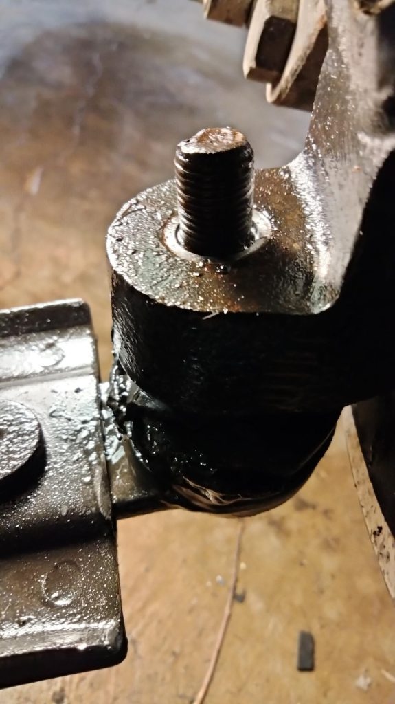
Inspect for special receiving components. MOOG’s lower-joint insert guidance describes cases where a knuckle insert adheres to the stud during removal. An unfamiliar sleeve is therefore not automatically debris to cut away. Identify whether it belongs to the knuckle and what the relevant procedure requires. Trying to separate the wrong interface can damage an otherwise reusable component or hide the reason the original removal behaved unexpectedly. Separate lack of movement from evidence of damage. Tool deflection, a housing entering at an angle, a changing gap or a distorted support surface should trigger a stop. A joint that moved partway and then jammed needs its own assessment; the new position may have changed adapter clearance. Do not assume that because it moved once, more of the same force must complete the job. Inspect the entire path and remaining travel.
Audit the setup before selecting a stronger tool
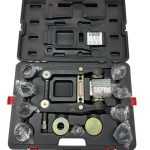
Check the tool's application and condition. Confirm that the separator or press is intended for the connection, that its contact points are correct and that the required adapters are present. Inspect the forcing screw and load-bearing surfaces for damage. Do not continue with a bent frame, deformed cup or slipping contact. A tool problem is not resolved by transferring more effort through it. OTC’s press instructions emphasize checking alignment of both tooling and components. On a press operation, verify the driver, receiver and support surfaces together. Confirm that the receiver has space for the moving part and has not bottomed out. On a separator, verify opening, reach and contact against the applicable instructions. A screw still having visible thread travel does not prove that the rest of the assembly has clearance.
- Recheck vehicle and component support independently. The press cannot safely substitute for control of a spring-loaded or suspended component. A knuckle that will move after release must not pull on brake hoses, sensor wiring or a driveshaft. If auxiliary support is used under the procedure, confirm that it has not lifted the vehicle away from its primary support. Correct any unsafe condition before returning to the stuck connection. Decide whether access is adequate to inspect and operate the tool. If you cannot see the driver contact or receiver position, a supported change in access may be necessary. Some jobs require removal of the arm or knuckle and bench work. That decision must follow the service procedure rather than a general assumption that on-car work is always possible. Better visibility and appropriate adapters can matter more than a higher-capacity press.
Escalate through evidence, then inspect the result
-
Begin by safely releasing stored tool pressure according to the equipment instructions. Keep clear of the potential release path. Do not strike a loaded tool or loosen an unrelated suspension connection to create movement unless the applicable procedure specifically requires that controlled operation. A sudden release can move parts farther than expected.
- The vehicle and assembly must remain supported when the tool is unloaded. Correct a verified preparation error before making another attempt. If a retainer was missed, remove it by the specified method.
- If the direction was wrong, rebuild the setup according to the actual housing design. If a cup was obstructing travel, select the documented adapter arrangement. These corrections are different from repeating the same attempt with additional force.
- Record the reason for the change so that the result can be interpreted afterward. Do not treat penetrating fluid as a universal answer. Product compatibility, access to the actual interface and protection of friction surfaces and boots all matter.
- Follow the relevant component and product instructions where chemical treatment is permitted. Spraying the visible exterior does not prove the product reached a seized fit. Keep chemicals away from brake pads, discs and other surfaces where contamination can create a separate repair requirement.
-
Do not introduce heat as a general next step. The receiving component's material, adjacent seals, grease, coatings and nearby systems can be affected. Without an explicit supported procedure, a torch or other heating method is an uncontrolled change to the repair.
- Likewise, there is no universal hammer size or striking point that is safe for every knuckle. A method shown on a different material or design does not establish suitability for this assembly. Avoid using impact operation or extending handles beyond what the tool permits.
- More energy can damage threads, adapters or the receiving component while leaving an overlooked retainer untouched. If a supplier's tool instructions permit a particular operation, that still needs to be compatible with the vehicle procedure and actual setup. Permission for one tool model should not be transferred to another tool with a similar shape.
- If the verified setup remains unsuccessful, obtain application-specific technical help. Provide the vehicle and part identity, photographs of the connection and the stage at which travel stopped. A workshop may use a different approved adapter, a bench setup or a supported destructive removal method when the surrounding parts can be protected.
-
Do not invent that method at home from a general instruction to cut the old joint out. The fact that the old part is scrap does not make the receiving component expendable. Delphi’s press-in replacement example shows a defined sequence for one application, including separation and press work.
- Use manufacturer examples to identify questions that your own procedure must answer. They do not justify borrowing one dramatic release step while omitting the support and tooling around it. A complete matching procedure is stronger evidence than a short clip of a stuck joint finally moving.
- After release, inspect the components rather than celebrating movement as proof of success. Check threads, the housing bore, the stud receiving surface and any inserts or retainers under the relevant criteria. MOOG’s stud-fit bulletin explains that a damaged receiving taper can require replacement of the knuckle.
- A new joint does not compensate for that damage. Do not hide gouges or an enlarged hole by grinding until the replacement appears to fit. Inspect parts exposed to the failed attempts.
-
A boot may be torn, a sensor wire stretched or a brake hose damaged even if the joint finally came free. Record these findings and revise the repair scope where necessary. Do not reinstall a component intended for reuse if the removal method has compromised it.
- The supported inspection and replacement criteria determine that decision, not the inconvenience of buying another part. Before installation, confirm the replacement part and all required hardware. Check the prescribed orientation, housing seating reference and retention features.
If the receiving component failed inspection, obtain the correct replacement before proceeding. Do not use an extra ring, adhesive or improvised shim to recreate an uncertain fit. Our installation acceptance guide explains what must be verified after the replacement is fitted.

Credit: m.youtube.com
If the vehicle must remain dismantled while parts or help are arranged, leave it secured in a suitable work area with detached components supported. Remove stored tool load. Mark which connections are incomplete.
Do not reassemble a known unsafe joint merely to move the vehicle under its own power. A recovery plan should account for the actual condition of the suspension. The right escalation produces a reasoned explanation: a retained part, unsuitable adapter, inaccessible setup, corroded interface or damaged receiving component.
It should also identify any damage caused during earlier attempts. That explanation guides the repair and prevents the same mistake at installation. A stuck joint is resolved when it is removed through a supported method and the remaining assembly can be evaluated safely, not simply when enough force makes something move.


Automotive reference information. Confirm specifications in the manual for your exact vehicle. Original replacement guides link to their research sources. About us