
Use a ball-joint separator only after confirming that it is the correct tool for the connection, that it can contact the intended surfaces and that the suspension is safely supported for release. A separator is not automatically the right tool for removing a press-fit joint housing from an arm.
Tool selection and setup come before applying force. There is no universal forcing-screw torque, hammer method or release direction for every vehicle and separator.
This guide explains how to evaluate the tool and prepare a controlled operation; the actual separation must follow the matched vehicle procedure and tool instructions. If you cannot identify either, obtain them before dismantling.

Credit: www.amazon.com
Match the separator to the connection and access
Identify the connection being separated. A tapered stud seated in a knuckle differs from a clamp-style connection or a press-fit joint housing. The tool must suit the specified operation, not simply fit somewhere around the joint. OTC’s 6297 separator page describes a particular tool intended to separate a joint from its support arm, with a stated adjustment range. That is a product specification, not proof that it suits every suspension. Confirm the jaw opening, reach and available operating space for the actual application. Fork-type and screw-operated tools also differ. OTC’s 6535 listing describes a fork separator with defined dimensions. A fork's fit and its effect on adjacent protective parts need consideration, particularly if the joint will be reused.
Do not choose a destructive separation approach merely because the replacement job on another vehicle used one. Check the vehicle's supported method and whether preserving the boot and stud is necessary. A tool that releases the connection while damaging a retained component has not achieved the required repair outcome. Measure or identify the relevant space before loading the tool. Check that the jaws can seat on their intended support, the forcing point aligns with the intended contact and the tool does not bear on a boot, sensor, hose or thin edge. Consider clearance throughout operation, not just while the screw is retracted. A nearby component may obstruct the tool as the connection moves. If the setup is angled or only partly engaged, select a suitable tool or obtain the prescribed access. Do not compensate with loose stacks of washers, improvised spacers or a longer handle.
Prepare the vehicle and tool before applying load
Follow the vehicle's lifting and component-support instructions. Secure the vehicle against movement and use appropriate stands or other specified support; a jack alone is not a safe work support. Determine what will move when the connection releases and how that movement is controlled. Suspension springs can retain significant force, and the correct support arrangement depends on the design. Keep hands and body clear of the expected movement path. If you cannot establish how the spring and supported components remain controlled, stop and use a qualified repairer. Inspect the separator before use. Look for damaged threads, distorted jaws, cracks, missing pins or other evidence that it is unsuitable. A tool borrowed from a rental kit needs the same inspection as a personally owned tool. Obtain the correct operating instructions and identify the permitted drive method.
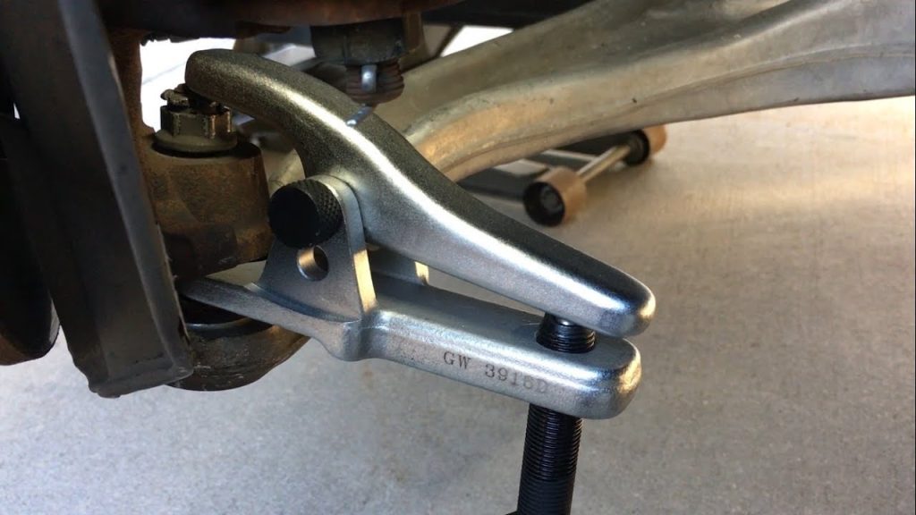
Lubricate tool threads only as the tool manufacturer specifies, and keep that maintenance separate from lubricating the vehicle's joint or taper. Wear the required eye protection and other protective equipment. Arrange lighting and access so that you can observe the seating without putting yourself in the release path. Plan protection and support for nearby components. A released knuckle or arm must not pull on a brake hose, sensor cable or driveshaft beyond its permitted movement. If the procedure calls for removing or supporting an adjacent part, include that step rather than assuming it will stretch enough. Know which retainers and nuts are removed, retained temporarily or replaced under the specific instructions. There is no universal rule for leaving a particular number of threads engaged. The required release control comes from the matched procedure, not from a generic photograph.
Check seating, apply only the permitted method and stop early
-
Read the complete operation before fitting the tool. Identify the jaws, pivot or adjustment points and forcing element. Confirm the selected setting is within the tool's range.
- A maximum advertised opening is not a target to exceed by partially engaging a pivot or backing a screw out too far. Use only the components intended for that separator. If the manufacturer requires a particular adapter or pressure piece, obtain it.
- Similar-looking parts from another kit are not automatically interchangeable. Position the separator without applying working force. Check the contact surfaces from a safe viewing angle.
- The reaction side must bear on the specified supporting surface, while the forcing side acts where the instructions require. Verify that the setup separates the intended connection rather than compressing the joint assembly against itself. An incorrectly placed tool can become tight without moving the taper at all.
- Resolve that uncertainty before increasing load. Do not use the tightening effort as a substitute for understanding the force path. Check clearance around the boot and retained components.
-
A boot that is pinched by the tool can be damaged even if the metal parts survive. A separator that slips toward a rounded edge may not have stable seating. If the correct tool cannot be positioned with the surrounding hardware in place, follow the prescribed access procedure.
- Do not grind the tool or the vehicle to make an improvised fit. Damage to a retained knuckle, arm or stud can change the entire repair scope. Apply only the drive method allowed by the separator instructions and vehicle procedure.
-
Do not assume that a forcing screw accepts an impact wrench or that striking a tool is permitted. Some equipment has very specific operating directions, and those cannot be transferred to another design. No generic hammer-strike recipe is provided here.
- If the instructions are missing or ambiguous, contact the supplier. A claim that a tool is heavy duty does not establish an unlimited force rating. Watch for loss of alignment, slipping, distortion or contact with an unintended component.
- Stop loading if any of these occurs. Follow the tool's safe unloading instructions before repositioning; do not reach into a loaded assembly to adjust a jaw. Keep the release area clear because a tapered connection can separate suddenly.
- The component-support plan should already control what happens next. A loud release is not a reason to bypass inspection, and a quiet release does not prove that the tool contacted the right surfaces. If the connection does not release within the supported operation, reassess the setup and application.
- Check whether the correct retaining hardware has been addressed and whether the connection was correctly identified. Do not add a pipe, heat the assembly or substitute an unapproved powered drive to overcome uncertainty.
-
A seized or damaged connection may need a different manufacturer-supported procedure or professional equipment. Our stuck-joint guide explains the separate diagnostic question.
- Continuing with more force is not an adequate plan by itself. Once separation is complete, safely unload and remove the tool according to its instructions.
- Inspect the stud, boot and mating area for damage relevant to reuse or replacement. Do not assume that a joint intended for reuse remains acceptable if the boot has torn or threads have been distorted.
-
Follow the component's repair criteria. Support the separated assembly throughout the remaining work.
- The separator has completed one operation; it has not verified the condition of the joint or finished the suspension repair. If the next operation is removing a press-fit housing, change to the correct service procedure and tool setup.
- OTC’s 7920 adapter instructions show a separate application-specific pressing arrangement and emphasize tooling alignment. That example is not a universal adapter recipe.
It illustrates why separating a taper and pressing a housing require different planning. Our knuckle-separation guide addresses the connection itself, while this article focuses on separator selection and controlled use.
Care for the tool and verify the completed repair
Clean the separator after use according to its maintenance guidance. Inspect threads and contact surfaces again before storage. Do not return a damaged tool to a shared kit without identifying the damage.
Replace worn or damaged service parts only as the tool manufacturer allows. Do not weld, grind or reshape a cracked jaw as a home repair. Store the instructions with the tool so the next user can identify the correct setup.
Keep required matching adapters together rather than mixing unmarked parts from different sets. Record a tool problem separately from a vehicle problem. A damaged forcing screw may indicate maintenance, misuse or another issue that needs assessment; it does not prove the vehicle joint was unusually defective.
Likewise, a stubborn connection does not justify using a compromised tool again. Ask the supplier for inspection or replacement guidance where needed. Tool condition is part of every future setup, not something checked only when a failure becomes obvious.
Complete reassembly using the vehicle and replacement-part instructions. Apply the required fastening and retention procedure and perform the specified checks of disturbed components.
Obtain alignment-related service where required. Do not drive merely because the separator worked and the wheel has been refitted.
If there is uncertainty about seating, a damaged retained part or an abnormal steering condition, resolve it first. A successful separator operation releases the intended connection without creating another defect; a successful repair also restores and verifies the complete assembly.


Automotive reference information. Confirm specifications in the manual for your exact vehicle. Original replacement guides link to their research sources. About us