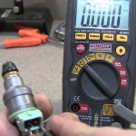

Fuel injectors receive electrical energy through the vehicle’s supply and driver circuits, while an engine controller or associated driver determines when and how they operate. The exact arrangement depends on the injection system. The fuel pump supplies pressurized fuel; it should not be confused with the electrical circuit that actuates an injector. On a common conventional port-injection arrangement, a switched supply is available and the controller completes the circuit in pulses.
That example does not describe every direct-injection or diesel system. Some injector drivers use more complex voltage and current control. The wiring diagram for the actual engine identifies the path; connector shape alone does not.
Think in three separate paths
The electrical supply path provides energy to the relevant circuit. The control path determines the timing and form of actuation. The fuel path brings fuel to the injector under the system’s required conditions.
These paths interact, but a successful check in one does not prove the other two are functioning. For example, a pump can operate while an injector circuit has an electrical fault. An injector can receive a command while the fuel supply is unsuitable.
A connector can show a voltage while the injector’s metered delivery is abnormal. Each observation answers a different question. This separation makes a workshop explanation easier to follow.
Ask whether a reported problem concerns supply, command or delivery. If the answer simply repeats “injector,” request the failed function. The repair scope should follow that function rather than the name of the assembly.
It also prevents misleading owner tests. Hearing the pump briefly does not establish injector power. Hearing a click does not quantify fuel delivery.
Seeing a dashboard warning does not locate a failed wire. Keep the observation and the conclusion at the same level of certainty.
The fuel pump supplies fuel, not the injector’s timing decision
The pump and injector have related jobs in fuel delivery, but they are not the same electrical component. Depending on the system, the fuel path may include different pressure stages and control devices. A simplified drawing that shows a tank connected to a rail leaves out important application-specific details.
Do not use it to choose test points. Bosch’s direct-injection overview describes delivery into the combustion chamber. That differs from port injection and helps explain why system identification matters before discussing pressure or actuation.
A universal pressure number is not appropriate across those designs. If a vehicle will not start, the question is not only whether a pump makes noise. The relevant procedure needs to establish suitable fuel delivery and electrical control under the required conditions.
Noise is an observation, not a pressure measurement. Likewise, a fuel-pressure result cannot certify the injector driver.
Our missing-power diagnostic guide focuses on an absent expected electrical condition. Use it when the concern is a circuit reading rather than assuming every fuel-system symptom comes from the pump.
A conventional switched-earth example
Pico Technology’s MPI guide describes an example in which the controller switches the injector’s earth path and current operates the solenoid. This explains why both sides of a connector must be understood before a meter reading is interpreted. One conductor may not be a permanent ground even though it is the switched side of the circuit. The pulse allows the controller to operate the injector for a limited interval.
A basic meter may average rapid activity rather than display the full event. A static voltage reading therefore may be insufficient to characterize operation. Appropriate waveform testing can answer a different question from a simple supply check. Do not use this example as a wiring instruction for an unidentified vehicle.
Pin assignments, supply switching and driver arrangements differ. Read the correct schematic and service procedure. An example circuit is useful for understanding the concept, not for deciding where to attach a jumper.
The distinction also explains why a disconnected connector may not behave like a loaded operating circuit. Test conditions belong in the result. “Measured at key-on with the connector unplugged” and “captured during cranking with the specified setup” are not interchangeable statements.
Direct-injection drivers can behave differently
Pico’s GDI voltage-and-current guide describes boosted opening voltage followed by a different holding strategy in its example. It also warns that testing can involve hazardous voltage. This is a clear reason not to describe every injector as a simple device that should receive steady battery voltage. The example does not supply universal waveform values.
Injector type, driver design and operating conditions affect interpretation. The correct vehicle procedure and suitably rated equipment are necessary. A measurement copied from another engine can be misleading even if both engines use direct injection.
Diesel systems add further application distinctions, including different actuator technologies. Do not infer a test method from the word “injector” alone. Identify the actual component and the prescribed procedure before resistance, voltage or activation testing.
For an owner evaluating a diagnosis, the practical question is whether the technician identified the system before interpreting the reading. Ask which specification or reference supports the conclusion. That is more useful than insisting every connector must show a particular universal voltage.
Fuses, relays and wiring must be traced from the diagram
The supply path may include circuit protection, switching devices, connectors and shared branches. Their exact arrangement comes from the schematic. Do not assume a relay with a familiar label supplies every injector, or that a fuse serving another fuel component protects the injector driver. Locate the actual path first.
A shared branch can help explain why several injectors show a similar problem, but it does not prove which component failed. A single affected circuit can point toward a local branch without excluding other causes. Patterns guide the next test; they do not replace it. Repeatedly replacing a fuse or swapping modules is not a substitute for tracing the fault.
A protection device opening may indicate a downstream problem that needs identification. Never increase the fuse rating to keep the engine running. Restore the designed circuit after the cause is established.

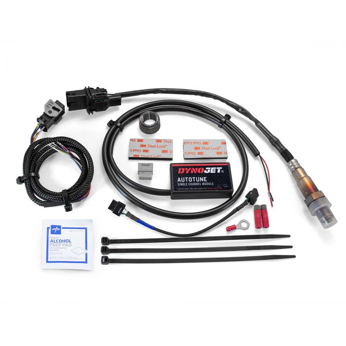
Credit: www.amazon.com
Voltage, current and command are different observations
Voltage describes an electrical potential difference between stated points. Current describes charge flow in the circuit. A command describes the controller’s requested operation.
These are related but distinct, so a result needs to state which was measured and how. A scan-tool command value is not automatically a physical measurement at the injector. An available voltage does not alone prove sufficient current under load.
An observed current pattern does not alone prove correct fuel quantity. A requested pulse does not guarantee the mechanical element responded properly. The investigation should connect the relevant observations rather than treating one as a complete functional test.
This matters when a report says an injector “has power but is bad.” That phrase can be reasonable shorthand only if the supporting tests identify the remaining fault. Ask for the actual evidence. A replacement should not rest solely on eliminating one possible cause while leaving several others untested.
Likewise, “no pulse” needs context. Confirm the operating condition, instrument suitability and system prerequisites.
A controller that is not expected to inject at that moment has not necessarily failed. Our injector-control guide explains the distinction between deciding to inject and supplying the electrical event.
Use the concept to read a diagnostic report
Look for the vehicle and engine identification first. Then find the circuit or cylinder tested, the operating state and the result. The report should name the relevant comparison. Without those details, a number or screenshot can be difficult to interpret later.
Ask whether the finding concerns a shared supply, an individual branch, the driver or the injector itself. Ask how the alternatives were distinguished. This does not require every conceivable test; it requires a defensible path from the complaint to the proposed repair. A specific measured failure is more useful than a list of parts that might be responsible.
If the fault is intermittent, ask whether it was captured during the complaint. A normal test afterward may leave uncertainty. Record that limitation rather than treating one normal reading as proof the problem never existed. The timing information can guide a later investigation.
After repair, request a repeat of the relevant check and assessment of the original symptom. Restoring a circuit reading is valuable, but the vehicle’s behavior should also be verified. Keep the findings with the invoice so any recurrence begins with evidence.
What not to infer from a simple test
A pump sound does not prove injector supply. A connector voltage does not prove correct flow.
A click does not prove sealing. A code does not identify a replacement by itself.
A clean scan does not prove every injector function is normal. Do not apply battery leads directly to an unidentified component.
Do not ground a driver wire to force operation. Do not use a heavy test load without an approved procedure.
Do not open a fuel connection to look for spray. These shortcuts can add damage or hazards without answering the intended question.
Instead, identify the system and the missing function. Use the correct service information and suitable equipment.
Separate fuel pressure from electrical actuation. Preserve the test conditions with the result.
Verify the original complaint after the repair.
The concise answer is that a supply-and-driver circuit provides injector energy, while control logic governs actuation.
Which wire, voltage or switching device performs that role is vehicle-specific.
Keeping that distinction prevents a useful general explanation from becoming an unsafe universal wiring rule.


Automotive reference information. Confirm specifications in the manual for your exact vehicle. Original replacement guides link to their research sources. About us