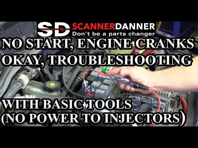

Reported “no power to the injectors” can mean several different things: no expected supply voltage, no switching command, insufficient current or simply a reading taken under the wrong conditions. Before replacing a fuse, relay or control module, establish exactly what was measured and what the vehicle’s wiring diagram says should be present at that moment. A meter reading across two connector pins is not the same as checking a documented feed against a specified reference.
Key-on, cranking and running conditions can also produce different results. An unplugged circuit may behave differently from one operating with its normal load. Record the test arrangement instead of treating the phrase “zero volts” as a complete diagnosis.
This article focuses on finding a missing electrical supply or distinguishing it from another problem. For the general relationship between the supply and the controller, see what sends power to fuel injectors. For a component that does not deliver fuel despite apparent electrical activity, use the separate injector-not-opening guide.
Do not jumper battery power to an unidentified injector circuit. Injector drivers can involve voltages and control methods that differ from a simple switched battery supply.
Incorrect probing can damage electronics or create an ignition hazard near fuel. Use vehicle-specific information and suitably rated equipment, or have the circuit assessed by a qualified technician.

Credit: www.breakerlink.com
First establish what is missing
Ask for the connector identification, pin, reference point, instrument mode and engine state used for the reading. Without those details, another person cannot reliably interpret the result. A “no power” conclusion made with the ignition off may be unsurprising, while an absent expected supply during the specified test condition is a different finding. Separate a supply check from a pulse check.
A conventional system may have an available feed while the controller briefly switches another part of the circuit. A basic meter may not display that short event in a useful way. The absence of a steady display does not prove that no command exists. Pico Technology’s MPI voltage guide describes the switched-earth behavior of its example system.
Its GDI guide shows a different drive strategy and warns of potentially hazardous voltages. These examples are reasons to identify the system first, not universal pin assignments for every injector connector. Also establish whether the complaint affects one injector, one group or all injectors.
That pattern can help locate a shared path, but it is not itself a diagnosis. Verify each comparison using the same appropriate method and conditions. A result from a different operating state is not a sound basis for declaring one connector abnormal.
Use the diagram to identify the supply path
The applicable wiring diagram identifies the relevant supply, switching arrangement, protection and connections. Do not assume the fuel pump and injectors share the same feed simply because both handle fuel delivery. A running pump does not prove the injector circuit has the expected electrical supply. Likewise, an injector electrical reading does not establish fuel pressure.
If the diagram shows a fuse in the relevant path, assess it using the specified procedure and correct circuit state. Visual appearance alone may not answer whether voltage reaches the required side under operating conditions. Do not replace a fuse with a higher rating. If protection opens repeatedly, investigate the fault rather than defeating the protection.
If a relay or controlled supply is involved, its inputs, command and output need to be understood. A relay clicking does not establish that its contacts deliver the required current. Swapping unrelated relays or bridging terminals without the diagram can create a new problem. The next check should be chosen from the circuit evidence, not from the ease of replacing a part.
Connectors and harness sections can introduce faults between a good upstream supply and the injector. Recent repairs, heat damage or a disturbed connection may provide inspection leads. Report them without assuming causation. The technician should isolate where the expected condition is lost and confirm that finding before repairing a particular section.
Why an unloaded voltage reading can mislead
A circuit can show voltage when it is barely loaded yet fail to deliver appropriately during operation. Fluke’s voltage-drop guidance explains the importance of testing electrical paths under relevant load. The practical point is that an apparently normal open-circuit reading does not certify the whole path. Conversely, a reading needs the correct reference and conditions before it can condemn anything.
The load used for a test must be suitable for the circuit. Do not connect an arbitrary bulb or other heavy load to a sensitive injector driver. A conventional test lamp is not automatically safe for every control output. Use the method and equipment specified for that system.
Poor reference connections can also distort a result. Record where the instrument’s reference lead was placed and verify the measuring setup. A bad measurement connection can look like a vehicle fault. Repeating the same incorrect setup on several connectors only repeats the uncertainty.
For a pulsed circuit, an oscilloscope or other appropriate diagnostic equipment can reveal behavior a basic display averages or misses. That does not mean every owner should probe it. Instrument ratings, probe selection and correct connection are part of the procedure. High-pressure fuel hardware and moving engine parts add separate access hazards.
Ask the technician what the measurement proves and what it leaves unresolved. For example, a verified feed at a connector may move the investigation toward control or the component itself, but it does not prove metered fuel delivery. Keeping the conclusion narrow prevents a single successful check from becoming an unsupported declaration that the injector is good.
Missing command is not automatically a failed computer
The controller must be in the appropriate operating state to command injection. Depending on the vehicle, missing engine-position information, authorization conditions or other faults can affect that decision. A controller that is not commanding an injector is not necessarily internally defective. The prescribed diagnostic sequence should establish the relevant prerequisites.
Check available fault information and relevant live data with equipment that supports the vehicle. Preserve the original results before resetting anything. A generic reader may not expose every status needed for the investigation. “No codes” on an unsupported or incomplete scan is not proof that the control system has no relevant information.
Before condemning a module, its required supplies, grounds, connections and the connected circuit need the appropriate checks. A downstream short can affect driver behavior. Installing another controller without resolving a verified external fault may leave the problem unchanged or create another failure.
Request the specific evidence for a module replacement. Our injector-control explanation covers the distinction between the controller’s decision and electrical actuation. Use that background to understand the report, while leaving pin-specific and waveform-specific conclusions to the correct service information.
Turn the findings into a verified repair
Document the original missing condition. Identify where it was measured. State the expected condition from the applicable procedure.
Record which repair restored it. Repeat the relevant check afterward.
If a fuse or connector was repaired, determine why it failed where the evidence allows. Do not describe repeated replacement of a blown fuse as a completed diagnosis.
If the issue was intermittent, note whether the original conditions were reproduced. A normal reading at one moment may leave an intermittent complaint unresolved.
| Inspect disturbed connectors and routed wiring using the service procedure. Do not leave pierced insulation, spread terminals or improvised jumpers as the finished repair. |
Those changes can introduce later faults. Have test connections restored appropriately.
Then verify the vehicle complaint, not only the electrical reading. A restored supply may be necessary without being the entire repair.
If the engine still runs poorly, continue from the remaining evidence rather than replacing injectors automatically. Preserve the before-and-after results for that next step.
The useful diagnosis is a specific statement such as “the expected supply was absent at this point under this condition, and this confirmed fault caused it.” The vague statement “injectors had no power” leaves too much unresolved. Precise testing protects both the repair decision and the electronics involved. A useful measurement example separates two reports. “The meter showed zero across an unplugged connector with the key on” describes a setup that still needs interpretation. “The documented supply was absent at the specified terminal during the required test, while the upstream point passed” gives a location and comparison that can guide fault tracing. Neither example supplies a universal pin number or voltage. The second is more useful because the expected behavior and reference are defined. Ask the workshop to preserve that level of detail in the report. It also helps when a repaired connection later becomes intermittent: the earlier test points and conditions provide a repeatable starting point instead of another general claim that the injectors lost power. If a result cannot be reproduced, record that fact and the conditions under which it originally occurred. Do not convert an intermittent observation into a permanent component failure without the supporting checks. A clearly documented uncertainty is preferable to a confident but unverified module diagnosis. Keep the original measurement notes available for any second opinion.


Automotive reference information. Confirm specifications in the manual for your exact vehicle. Original replacement guides link to their research sources. About us