
A multimeter checks electrical properties, not complete injector health
Identify the injector and the intended measurement
A multimeter can help with certain injector electrical checks when the correct service procedure permits them.
It cannot measure spray pattern, calibrated fuel delivery or sealing merely by touching two terminals.
Start with the vehicle, engine and injector design.
Decide whether the question concerns the component’s resistance, the supply circuit or another specified electrical measurement before choosing a meter mode.
Obtain the procedure before disconnecting anything
The service information must define the circuit state, connections and expected result.
Do not assume every injector can be unplugged and tested in the same way.
Direct-injection and diesel systems can have different actuator and driver requirements.
If the applicable procedure or equipment rating is unknown, obtain it or use a qualified technician rather than guessing at the connector.
Resistance testing requires a de-energized, isolated circuit
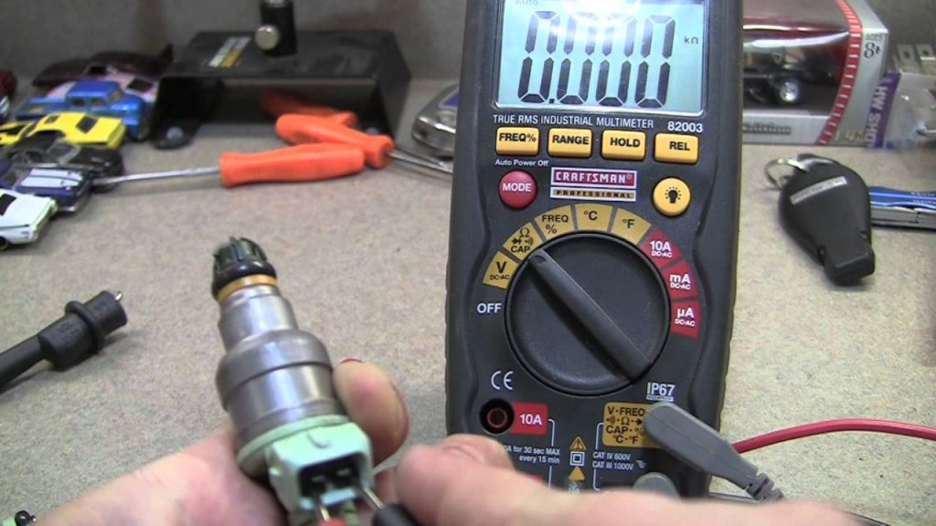
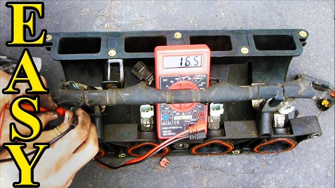
Use resistance mode only in the circuit condition required by the manufacturer; never use it on an energized circuit.
The procedure must establish what is disconnected and where the measurement belongs.
Do not use a universal internet resistance range for every injector.
Record the actual result, units and specified conditions so the comparison remains meaningful.
Credit: m.youtube.com
A continuity beep is not a complete resistance assessment
A continuity function uses the meter’s own threshold to signal a conductive path.
That threshold is not an injector manufacturer’s pass/fail limit.
A beep cannot certify the winding or the component’s full electrical condition.
| Use the measurement and comparison required by the service information, and keep the interpretation narrower than “the injector is good.” |
A meter cannot confirm a fuel leak by itself
Internal leakage and external fuel escape require different, suitable investigation; a resistance result does not measure either.
If fuel is visible outside the system, stop unsafe operation and arrange assessment without touching suspected spray or loosening a pressurized fitting to observe it.
Comparisons need the same conditions
When comparing units, confirm that they are the same specified type and tested under equivalent conditions.
Temperature and connection quality can matter to the applicable procedure.
Similar readings do not prove that every injector meets specification.
A difference is a diagnostic lead to interpret, not automatic authorization to replace the outlier without checking the setup.
Keep the component and circuit questions separate
A component resistance check is not the same as checking the harness supply.
Label which side of a disconnected connector was tested.
Record the reference point for voltage readings.
State whether the engine was off, cranking or running.
Without that context, a number such as zero volts can be misunderstood and lead to the wrong repair.
Prepare a useful test record
Record the vehicle identification. Record the engine.
Record the injector or cylinder. Record the meter mode.
Record the units. Record the connection points.
Record the operating state.
Identify the service specification.
Note the measured result.
Note relevant temperature conditions.
Check whether the result is repeatable.
Preserve the original fault information.
State what the reading proves.
State what remains untested.
This record is more useful than a photograph of an isolated display.
Another technician can see whether the method answers the actual question.
A bare number without context should not become a replacement decision.
Do not invent a routine testing interval
An injector resistance check is not automatically scheduled maintenance for every vehicle.
Use the actual maintenance requirements and the complaint being investigated.
Unnecessary disconnection or probing can disturb otherwise sound connections, so choose the test because the diagnostic procedure needs it rather than because the odometer reached a round number.
Understand the limits of each instrument function
Resistance concerns an electrical characteristic under specified conditions. Voltage concerns a potential difference between identified points.
| Continuity gives a threshold-based indication. |
None directly measures fuel quantity.
None directly shows atomization.
None alone verifies closed-injector sealing.
Delphi’s common-rail electrical guidance distinguishes resistance, inductance and insulation checks for supported solenoid injectors.
That illustrates why a basic meter is not equivalent to every dedicated electrical test.
Equipment capability and the injector-specific procedure determine which question can be answered.
Use suitable leads and avoid damaging terminals
Inspect the meter and leads according to the instrument instructions. Select the correct mode and input sockets for the intended measurement.
| Use the connection method specified for the vehicle. Do not force oversized probes into terminals. |
Do not pierce insulation casually and leave the damage as part of the finished circuit. A poor test connection can produce a misleading result.
Confirm the setup before blaming the vehicle.
If access is unsafe or the correct adapter is unavailable, obtain suitable equipment instead of improvising around moving parts or fuel hardware.
Keep voltage checks within the approved procedure
A driver circuit may not behave like a steady battery supply. A basic meter can average rapid switching and conceal its shape.
The correct reference point matters. The correct operating state matters.
The connected load matters. Equipment ratings matter.
Do not apply a generic test lamp or jumper to an unidentified driver output.
Pico’s MPI waveform guide demonstrates a switching assessment for its example system.
That is a different measurement from a static meter display, and its settings are not universal.
Use appropriate waveform equipment through a qualified procedure when the diagnostic question requires it.
Interpret the result before selecting a repair
An out-of-range resistance needs confirmation
Recheck the part identification and specified conditions.
Verify the measuring setup.
Compare the result with the correct application limit rather than another engine’s figure.
If the finding is confirmed, document it as an electrical defect under that test; do not add unsupported conclusions about spray quality or the cause of every vehicle symptom.
A normal resistance does not end the diagnosis
The winding can satisfy one specified comparison while another function remains faulty.
The harness, driver and fuel conditions are separate questions.
A delivery or sealing problem may require another test.
If the original complaint persists, continue from the unresolved evidence instead of declaring the whole injector and fuel system healthy from one normal reading.
A missing voltage needs circuit context
Determine what voltage should exist at the stated point during the chosen condition.
Distinguish a feed check from a switching check.
A disconnected or inactive circuit may not behave as expected by an improvised test.
Our no-power guide explains how to make the missing-condition claim precise before choosing a fuse, relay or controller.
Credit: m.youtube.com
An unloaded reading may miss a supply problem
Fluke’s automotive guidance explains why voltage-drop testing under relevant load can reveal circuit faults.
That does not authorize attaching any convenient load to an injector driver.
Use the load and method approved for the circuit.
| A seemingly normal unloaded reading should not be treated as proof that every connection can support operation. |
Do not use electrical checks as a spray test
Do not remove the rail and energize injectors over an open container to extend the meter test into a fuel demonstration.
Proper delivery testing needs controlled conditions and containment, and an improvised spray does not provide calibrated evidence of injector performance.
Do not force operation with a battery
A multimeter and a battery are not interchangeable diagnostic tools.
Applying direct power can bypass the intended driver control.
The correct activation requirements depend on the injector.
Our battery-test guide explains why a click cannot certify flow or sealing and why an unidentified component should not receive an improvised electrical pulse.
When dedicated testing is the appropriate next step
Ask what remains unknown after the electrical check.
A specialist may need an appropriate component or system test.
The method must match the injector design.
Delphi’s service guidance places injector assessment within correct system servicing.
A report should connect the result to the proposed repair rather than merely state that the component was put on a machine.
Finish with verification of the original complaint
Restore test connections correctly. Confirm connectors are secured.
Address any test-related damage appropriately. Perform required installation steps if anything was removed.
Check the repair using the prescribed procedure. Retain the initial readings.
Retain the applicable comparison.
Record the repair.
Repeat the relevant electrical check.
Reassess the vehicle’s original symptom.
Note any condition that could not be reproduced.
Keep those limitations in the service record.
A meter is useful when its measurement answers a defined electrical question.
It becomes misleading when a beep or a single value is called a complete injector test.
Use the correct specification, protect the circuit and request the additional evidence needed for fuel-delivery or sealing conclusions. If the meter display is unstable, do not average the numbers mentally and declare a pass. First determine whether the procedure expects a stable value in that mode. Check the connections and instrument setup using the approved method. An intermittent electrical condition and an unsuitable measurement technique can both produce confusing displays, but they call for different responses. Preserve what was observed and let the next test resolve the distinction. This is especially important when a replacement would require substantial dismantling: the electrical conclusion should be sound before the repair scope is expanded.


Automotive reference information. Confirm specifications in the manual for your exact vehicle. Original replacement guides link to their research sources. About us