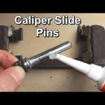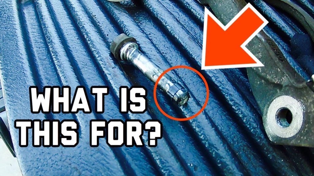

The upper brake-caliper guide pin is the one specified for the upper location on that exact caliper assembly. There is no reliable universal rule that the rubber-sleeved pin, the longer pin or the plain pin always belongs at the top. Some pin pairs differ; others may be interchangeable when the manufacturer explicitly identifies them that way. Confirm the arrangement with the vehicle service diagram and the correct pin-kit instructions before assembly. If the pins have already been mixed, do not choose their positions by trial and error.
This question is easiest to prevent before dismantling, but it can still be resolved afterward with careful identification. You need the vehicle's precise brake application, the caliper or bracket identification, and a diagram that distinguishes its locations. A picture of a similar caliper from an online listing is weaker evidence. Brake packages can vary within one model year, so matching only the vehicle name is insufficient.
Incorrect placement may create a fit or movement problem even when both bolts can be tightened. A pin that enters a hole is not necessarily correct for that hole. The objective is the intended guided movement with the proper bushings, boots and fasteners, not simply making the parts fit back into the space. If the documentation remains ambiguous, leave the vehicle out of service until the arrangement is confirmed.
Understand what the pin differences are telling you
A floating caliper moves relative to its support through guide elements while the pads clamp the disc. Those elements are engineered parts of the assembly, not generic bolts chosen only for their thread. HELLA explains floating-caliper guide arrangements and the importance of free movement. The same guidance shows that caliper designs can use different guide and sleeve configurations. That is the reason visual differences deserve attention rather than a universal top-or-bottom answer. A pair may differ in shaft length, machined flats, sleeve location, surface treatment or another detail. A rubber damping sleeve is part of a particular design and should not be discarded because it makes installation less convenient. Conversely, a missing sleeve does not prove the manufacturer intended a plain pin; the old part may be incomplete.
Compare the parts with the specified kit contents and service illustration. Treat wear and prior repair errors as possibilities. The guide pin and the bolt that secures the caliper are not always the same component. Some assemblies use a separate fastener threaded into a sliding pin, while other arrangements look different. A torque instruction for the mounting bolt does not automatically apply to every nearby fastener. When asking for help, distinguish the sliding shaft, its boot or bushing, the securing bolt and the caliper bracket. Clear names reduce the chance of receiving a correct answer for the wrong part.
Do not confuse guide-pin location with pad retaining pins on a fixed caliper. A fixed-caliper retaining pin may pass through pad hardware without serving as a floating guide. If the brake does not match the assumed design, stop and identify it before selecting a diagram. A search result headed caliper pin can refer to either role. The physical function matters more than the broad product name. Left and right also complicate pictures. A diagram may show one side of the vehicle, a component on a workbench or an exploded orientation chosen for readability.
Top on a rotated photograph is not necessarily upper on the installed brake. Identify the wheel position and relate the drawing to fixed landmarks on the actual assembly. The hose connection, mounting ears and bracket shape can help orient the diagram, but the instructions remain the authority. Likewise, leading and trailing are not universal substitutes for upper and lower. Their relationship depends on where the caliper sits around the disc and how the wheel rotates. Do not translate those labels mentally without checking the illustration. If a parts sheet uses a different orientation convention from the workshop manual, obtain clarification rather than selecting whichever interpretation looks most familiar.
Recover the correct order when the pins are already mixed
Collect the vehicle identification, model year, axle position and any relevant brake option before searching a parts catalogue. Record casting numbers and the part numbers on the installed or replacement assembly where accessible. A casting identifier may not be a complete service part number, so use it as supporting information rather than assuming it settles fitment. The supplier or manufacturer can help cross-reference an uncertain assembly. Find the exact service illustration and read its associated notes. Look for separate callouts for upper and lower pins, different part numbers, specified bushings and any installation arrows or dimensions. Check whether the diagram applies to the front or rear axle and to the relevant side.
A general overview drawing may not show every detail needed for reassembly. If the manual sends you to a separate kit instruction, read that document as part of the procedure. Compare both pins on a clean surface without modifying them. Note the length, sleeve, grooves and any markings, and photograph the pair beside its labelled packaging if available. Use those observations to match the documented components. Do not grind a pin, remove rubber or enlarge a bore to make an assumed position work. A mismatch is evidence to investigate, not a reason to alter a safety component.
If the opposite side has not been disturbed, it can provide a useful observation, but it is not definitive proof. The vehicle may have undergone an earlier incorrect repair, or left and right arrangements may need to be read separately. Photograph that side before moving anything and compare it with the documentation. Agreement between the correct diagram, the kit and the undisturbed assembly is stronger than any one clue alone. When documentation lists identical pins for both locations, confirm that the kit really contains that specified pair and that no separate sleeves or bushings differ by position. Interchangeability must come from the application information, not from two pins appearing similar in a photograph. When documentation lists different pins, keep their identities separate throughout cleaning and installation.
A pair supplied in one bag can still contain position-specific parts. Ask a supplier a precise question if uncertainty remains. Provide the vehicle identification, axle, caliper part number, photographs of the two pins and the diagram reference, then ask which callout belongs in each installed location. Avoid a broad question such as whether the rubber one goes up; that invites a generic answer. Request the supporting application instruction when possible. Save the reply with the part number rather than relying on a verbal memory. An aftermarket remanufactured assembly may have its own approved supplied-hardware instructions.
Reconcile those with the vehicle application and do not automatically transfer a pin from the old assembly because its colour looks familiar. If the supplied components conflict with the stated application, resolve the discrepancy before use. A replacement is not validated solely by bolting onto the bracket. For future work, service one location at a time when the procedure permits and label a clean parts tray with the actual wheel position. Take an installed-orientation photograph before removal. Those habits preserve evidence without relying on memory. They also make it easier to see a missing boot, unusual wear or an earlier mismatch before components are mixed together.
Install and check the confirmed arrangement without shortcuts
Once the positions are established, inspect each pin and its matching guide components before installation. A deeply corroded, damaged or distorted pin is not restored to its original dimensions by adding lubricant. Check the protective boots and any damping sleeves for damage or swelling. Follow the prescribed replacement criteria and use the correct service parts. Position identification cannot compensate for a defective component.
Cleaning and lubrication requirements are design-specific. HELLA describes a thin suitable lubricant film for the internal guide arrangement in its example, while ATE workshop guidance includes guide-sleeve systems whose internal pins and sleeves must not be greased. These are not contradictory universal rules; they describe different arrangements. Read the instruction for the fitted design before applying a familiar tube of grease. Do not add lubricant to a system specified to run dry.
Where lubrication is specified, use the correct product with compatibility for the actual rubber and guide materials. The words high temperature or brake grease alone do not establish that compatibility. Keep lubricant off the disc and pad friction material. For the product-selection question, see choosing lubricant for brake-caliper pins. That article addresses materials and application limits rather than deciding upper and lower placement.
Seat the boots or bushings as the instructions require and make sure they are not twisted or trapped. Verify the intended guide movement before completing the assembly. A pin that binds or a boot that will not sit correctly calls for investigation of the part, location and preparation. Do not treat excessive fastener force as a way to pull a wrongly assembled guide into position.

Credit: community.cartalk.com
Use the application-specific fastener tightening procedure, including new fasteners or locking provisions when required. Do not transfer a bracket-bolt torque to a smaller slide-pin fastener. Keep the caliper supported during the work so the hose and wiring are not strained. Check the rest of the assembly for proper pad seating and undamaged routing before restoring the wheel.
After reassembly, complete the vehicle's stationary brake checks before any movement. Proper pedal response, no leakage and correct brake release are separate requirements. A quiet brake on the first press does not prove the pin arrangement is correct. If abnormal drag, pulling, noise or heat appears, stop using the vehicle and have the installation inspected.
If a workshop is correcting mixed or damaged pins, ask the invoice to identify the fitted kit and any affected bracket or caliper parts. The FTC advises obtaining a clear written repair estimate and documentation. That record helps if a later parts lookup is needed. It is more useful than a note saying the pins were swapped until they felt better.
The answer to which pin goes on top should therefore be traceable to an exact application and illustration. Once that evidence is available, the decision becomes straightforward. Without it, rubber sleeves, pin length and internet anecdotes remain clues rather than instructions. Leave the brake unassembled or arrange qualified help rather than turning an uncertain position into a road test.


Automotive reference information. Confirm specifications in the manual for your exact vehicle. Original replacement guides link to their research sources. About us