A suitable test light can indicate power or a ground path at an identified conventional fuel-pump relay circuit. It cannot, by itself, prove that a relay or pump is healthy. Begin with the vehicle wiring diagram and the tester’s instructions; do not probe an engine-computer output with an arbitrary lamp.
The safest useful question is specific: “Is voltage present at this documented relay supply or output while the pump is supposed to run?” That is different from bridging terminals, applying power to a control wire or testing an unidentified socket.
Check the tester before using it
Test lights vary in current draw, voltage rating and intended use. A small LED indicator and an incandescent lamp are not interchangeable loads. Read the instructions for the exact model instead of assuming every automotive test light is safe on every low-voltage circuit.
For example, the Innova 3410 instructions describe power and ground indications but explicitly prohibit use on computer circuitry. That limit matters at a relay controlled by an electronic module. Use the manufacturer-specified measurement tool for those control terminals.
Identify supply, switched output and control separately
Use the service wiring diagram to identify each circuit at the relay socket. The load supply and switched output are not the same as the relay coil’s command and return. Pin numbers, relay orientation and socket views can be misread, particularly when comparing a component diagram with a harness diagram.
Confirm the vehicle actually has the conventional relay arrangement being tested. A module-controlled pump or integrated solid-state switching circuit may require scan data, a multimeter or an oscilloscope procedure instead. Do not force a relay test onto a system that does not use that architecture.
Establish when the output should be live

Credit: www.wikihow.com
A pump may receive a brief prime command and then stop until further conditions are met. Position the test and observation method according to the service procedure rather than inspecting the lamp long after the activation window has ended.
The relevant state may be key-on, cranking, running or a supported scan-tool output test. Secure the vehicle and keep leads clear of moving components. If the required test state cannot be achieved safely, have a technician perform it rather than create an uncontrolled activation.
What a power-side indication means
On a circuit approved for the lamp, use the specified reference and terminal adapter. A lit lamp indicates a path capable of operating that particular tester. It does not prove that the circuit can supply the pump’s working current or maintain acceptable voltage under load.
A dark lamp also needs context: verify the tester, reference connection, circuit identity and commanded state before concluding that power is absent. A blown fuse, missing feed, uncommanded relay and damaged relay contact can lead to different follow-up checks despite the same visible result.
Why ground and control probing needs extra care
Connecting a tester to battery positive changes the test: it seeks a return path and can introduce current into the terminal being probed. Do not apply that arrangement to an unknown control wire or electronic module output. A circuit diagram alone is not permission to exceed the controller’s permitted test load.
Use a high-impedance meter or other tool when the service procedure requires it. Avoid forcing probe tips into terminals, which can spread contacts. A connector damaged during diagnosis can become a new intermittent fault after the original problem is repaired.
Use measured voltage when the lamp is inconclusive
Brightness is not a calibrated voltage measurement. A feed can operate a small test lamp while suffering excessive voltage loss with the pump connected. Conversely, a control signal may be pulsed rather than steady, making a simple visual interpretation misleading.
Delphi’s voltage-drop procedure explains the importance of checking the power and ground paths under appropriate operating conditions. Use the vehicle’s limits and suitable adapters; do not import a generic pass value into every system.
Distinguish a failed relay from a missing command
A relay click demonstrates movement, not contact quality. No click does not automatically condemn the relay either: the coil may lack its required feed or command. A valid diagnosis follows the documented circuit from supply through control and output.

Credit: www.youtube.com
If an output test or temporary bypass is part of that manufacturer procedure, see fuel-pump relay activation and bypass limits. Do not leave a jumper installed as a repair or bypass a collision-related shutdown.
Record the result in a useful way
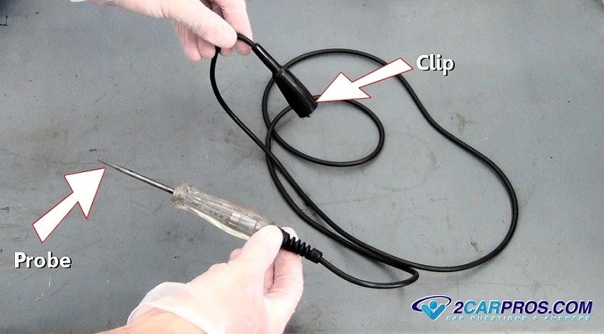
Credit: www.2carpros.com
Write down the terminal identification, ignition or command state, reference point, tester model and observed result. “No light at the pump relay” omits too much information to support a replacement decision.
After repairs, restore the normal connections and verify the original symptom with the system controlling the pump normally. Test-light checks contribute to that diagnosis; they do not replace fuel-delivery measurements or final leak and function checks.


Automotive reference information. Confirm specifications in the manual for your exact vehicle. Original replacement guides link to their research sources. About us