
A suspension ball joint is an articulated connection that lets linked suspension components change angle while remaining attached. On many passenger vehicles, it connects a control arm with the wheel carrier or steering knuckle. Its name describes the enclosed ball-and-socket arrangement, not a loose ball you can normally see beneath the car.
The exact shape, mounting and location depend on the suspension design. Identification matters because several neighboring parts can look similar. A tie-rod end also uses a jointed connection, but it belongs to the steering linkage and should not automatically be counted as the suspension ball joint named on an estimate.
A rubber bushing, wheel bearing and constant-velocity joint perform other jobs. Knowing which assembly is being discussed makes parts ordering and repair explanations much clearer. This guide focuses on recognizing and naming the component.
For the movement and force transfer inside the system, see how a ball joint works. If you are investigating a noise or steering change, identification is only the first step; a correctly performed inspection is still needed before deciding the part has failed. Do not crawl under an unsupported vehicle or pull on suspension parts just to confirm a name.

Credit: en.wikipedia.org
Recognize the assembly rather than searching for a visible ball
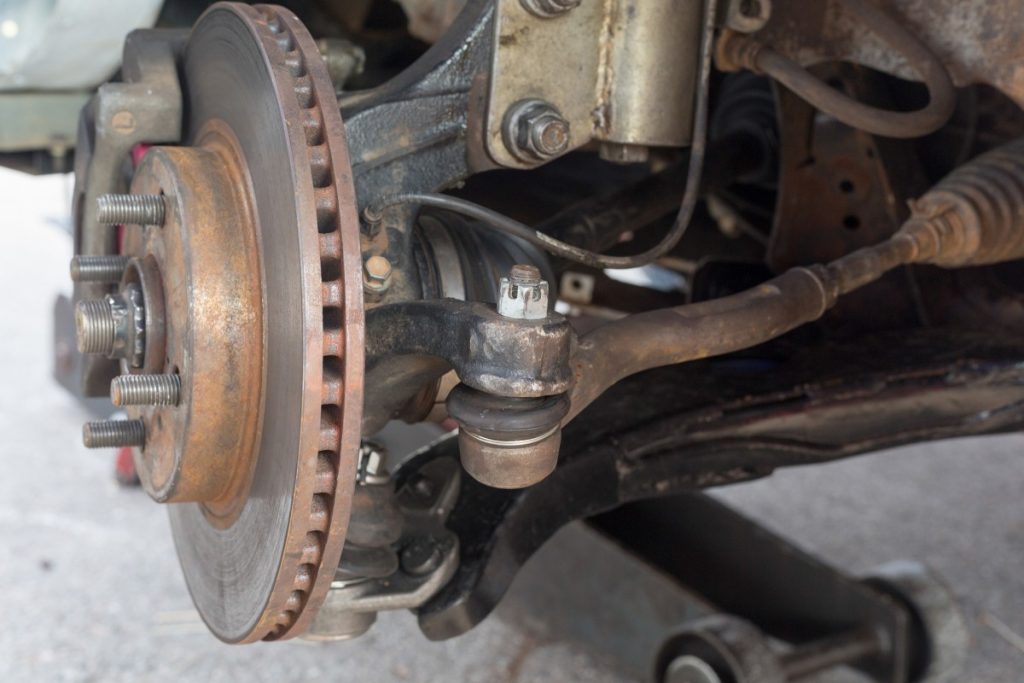
The ball is enclosed inside a housing. What you can often see is a housing or the end of a control arm, a stud connection and a protective boot around the moving area. Dirt, shields, wheel position and the suspension layout can conceal some of those features. A small grease fitting may be present on a serviceable design, but its absence does not mean the component is not a ball joint. MOOG’s explanation of socket-style chassis parts shows why similar-looking joints appear in several steering and suspension components. The shared internal concept does not make those parts interchangeable.
Identify what the component connects and what the vehicle diagram calls it. Appearance is supporting evidence, not a substitute for the application information. A replacement part on a retailer’s page may also look different from the installed original while being intended for the same application. Conversely, two nearly identical photographs may represent different tapers, mounting sizes or sides. Use the vehicle details and part catalogue rather than choosing by visual resemblance. Keep the exact description and part number together when asking a repairer for clarification.
Name the visible features and their different jobs
- The housing contains the working joint. The stud provides the connection to the adjoining component. The protective boot helps shield the moving region from contamination. Mounting hardware secures the assembly according to its design. These features should not be confused with one another when discussing damage.
- A split boot, a loose attachment and internal wear are different findings even if they occur at the same location. The boot is not the structural connection that holds the wheel assembly together. Its condition matters, but replacing or covering it does not automatically repair internal damage. Likewise, a tight-looking nut cannot establish that the enclosed bearing is sound. An inspector needs to assess the relevant interfaces and compare them with the applicable criteria.
- A photograph can document visible condition without revealing everything inside. ZF’s suspension-ball-joint overview describes several mounting arrangements, including integrated and separately mounted joints. A joint may therefore be visible as a replaceable component or form part of a larger assembly. Do not assume that every housing can be pressed out or that every catalogue listing represents a separate service part. The vehicle and component instructions determine the supported repair.
A flange with bolts, a press-fit housing and a stud retained in a knuckle are also different interfaces. The fastener you see may secure only one of them. If an estimate says the ball joint is loose, ask whether the movement is inside the socket, at the stud connection or where the housing is retained. That precision helps distinguish a worn part from a damaged or incorrectly secured mounting.
Sealed and greaseable describe maintenance provisions
A sealed joint is designed without routine replenishment through an owner-service fitting. A greaseable joint provides a manufactured lubrication point and requires the specified service. Those descriptions do not by themselves establish quality, remaining life or whether the joint is currently safe. A replacement may use different maintenance provisions from the original component, so read the installed part’s instructions rather than assuming the vehicle has never changed. Do not puncture a boot or drill a housing to make a sealed design accept grease. A purpose-made low-profile service connection is different from an improvised opening. If a fitting cannot be identified, ask the component supplier or repairer. Our guide to ball-joint lubricant explains product terminology once the service provision has been confirmed.
Supplied grease does not answer every installation question
A new joint may contain lubricant, but the installation instructions determine whether additional service is required before use. Do not infer readiness from seeing grease near the boot or from a general claim that replacement parts arrive prefilled. The contents and service requirements can vary by product. Keep packaging and instructions with the part until installation is complete. The same caution applies to accessories supplied in the box. A new nut, retaining ring or fitting may have a specified role and should not be replaced casually with familiar old hardware. Ask the installer to identify which components are renewed and which are retained. Understanding the assembly helps explain the repair without turning a definition article into an unsupported installation procedure.
Distinguish a ball joint from nearby components
- A tie-rod end links the steering system to the wheel carrier through its own joint arrangement. A control-arm bushing generally provides a different type of pivot or compliant connection. The wheel bearing supports wheel rotation, while a constant-velocity joint transmits drive through changing angles on applicable vehicles. These parts may be close together and can share some symptoms, but they are not alternate names for the same repair. When looking at a diagram, follow the complete component rather than stopping at a rubber boot. Does the link run toward the steering mechanism, toward the body or subframe, or along a drive shaft? What does the labelled assembly connect? Use those relationships to orient the conversation. Do not rely on a universal rule that every round boot near a wheel belongs to a ball joint. An invoice can use abbreviated language that needs clarification. Ask for the corner, upper or lower position where applicable, assembly name and part number. If the bill includes a control arm, find out whether its joint is supplied within that assembly. If it includes a tie-rod end, do not assume the suspension ball joint was also replaced. Clear naming prevents mistaken conclusions about what remains original.
Locate it using the actual suspension layout
- ZF’s control-arm description explains the link between the wheel carrier and vehicle structure in independent suspension. The ball joint is one possible connection within that arrangement, but the layout varies. A common strut front suspension may have a lower suspension joint without a conventional upper control-arm ball joint. A double-wishbone arrangement commonly has upper and lower connections. Those are examples for orientation, not a universal count for every car.
- Rear suspensions also differ. Some use articulated joints in independent link arrangements; others do not mirror the front layout. A solid rear axle should not be assigned the same wheel-end joint pattern as an independent front suspension simply because the car has four wheels. Use a diagram specific to the vehicle and axle. Our joint-count guide explains how to build an accurate inventory.
For parts identification, start with the vehicle identification number and the relevant production or option details requested by the catalogue. Check whether a previous repair or suspension modification changed the installed assembly. If the catalogue and vehicle disagree, resolve the difference before ordering. A photograph of a similar model cannot settle an option-specific fitment question. For a workshop discussion, ask the technician to show the named component on an accessible diagram or a safely positioned vehicle.
You do not need to dismantle anything to understand the estimate. Request a photograph of the actual defect if that helps, while recognizing that internal condition may require a measurement rather than a picture. Identification and diagnosis are separate steps. For maintenance records, write down the precise component rather than front-end parts replaced. Record which side, assembly and part number were used.
This is particularly useful when one side has been repaired and the other retains original equipment. The next service can then use the instructions for the actual installed component, including any lubrication requirement. If a parts listing offers several alternatives, ask which specification distinguishes them. Production dates, axle options and mounting details can matter even when the advertised vehicle name matches.
Resolve the choice before approving an order. A ball joint is therefore best understood as a particular articulated connection within a defined suspension, not a generic item selected from a photograph. Recognize the housing, stud and protection, identify the linked components, and confirm the application in the correct information. That gives you enough context to ask useful questions without assuming that appearance alone proves fitment, condition or repairability.


Automotive reference information. Confirm specifications in the manual for your exact vehicle. Original replacement guides link to their research sources. About us