A suspension ball joint allows connected parts to change angle while retaining a defined connection between them. Its rounded stud end articulates inside a socket, so the suspension can move through its intended travel and, at a steering wheel, accommodate changes in steering angle. It must permit that motion without allowing uncontrolled looseness that changes wheel location. Freedom to articulate and freedom to rattle are not the same requirement.
The joint works as part of a system of arms, links and mounting points. It does not determine the wheel’s entire path by itself. The surrounding geometry controls how the wheel moves as the suspension rises, falls and steers. The joint supplies a connection that can accommodate the changing angle while transmitting the loads assigned to it by that design.
This guide explains that mechanical behavior. For locating and naming the component on a vehicle, see our ball-joint identification guide. The explanation here is not an inspection procedure: understanding the concept does not establish a universal lifting method, allowable-play value or replacement specification.
Think of an articulated connection, not a loose hinge
A simple door hinge is mainly arranged around one rotation axis. A ball-and-socket connection can accommodate angular movement in more than one direction within its designed range. That makes it useful where suspension and steering movements combine. The available range is still limited by the component geometry, protection and installation. It should not be treated as an unrestricted swivel that can be forced into any angle.
Imagine a control arm moving through its travel while the wheel carrier changes orientation. A rigid connection at every interface would prevent the intended movement or force other parts to distort. The articulated joint allows the relationship between the linked parts to change angle. At the same time, it retains the connection rather than allowing the parts to translate freely apart.
ZF’s control-arm explanation describes arms as links between the wheel carrier and vehicle structure in independent suspension. The shape and arrangement of those links determine the wheel guidance. A ball joint is therefore one element in the geometry. It is not a separate steering device that independently decides which direction the tire points.
This distinction helps explain why replacing a joint must preserve the intended application and mounting. A part that physically fits can still have an unsuitable range, dimensions or connection. Correct fitment is about the complete mechanical requirement, not merely matching a hole diameter or thread. The service information and application catalogue remain necessary even when two parts appear similar.
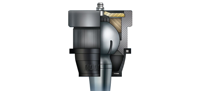
Credit: www.moogparts.com
Motion passes through the socket; forces pass through the assembly
Inside the joint, the stud and bearing arrangement provide the working contact that allows articulation. The housing and attachment interfaces retain the assembly and transfer loads to the connected parts. MOOG’s socket-style construction overview identifies the housing, stud, bearing elements and lubricant as parts of that arrangement. Their specific materials and construction vary by product; one manufacturer’s internal design is not universal. During normal suspension movement, the joint must accommodate changes in angle while supporting the forces applied through its connections. Those forces are not limited to the direction in which the car is moving. Braking, cornering and road inputs create different demands across the suspension. The exact distribution depends on the design, so the statement that every ball joint carries the vehicle’s weight is too broad. A useful distinction is between the allowed rotational or angular motion and unwanted movement at an attachment or within a worn bearing.
The joint can be designed to articulate smoothly while remaining precisely located. If a mounting becomes loose, that introduces movement at a different interface. If the internal bearing wears, the connection may develop unintended clearance. Both deserve assessment, but they are different defects. The stud nut or other retaining hardware secures the specified external connection. It is not generally an adjustment that removes internal socket wear. Increasing its torque cannot replace material lost inside the bearing. Likewise, a correctly tightened attachment does not prove that the internal joint is sound. Installation checks and condition inspection answer separate questions.
The housing, bearing, lubricant and boot have different roles
The housing provides the structure around the working joint and connects it to the surrounding assembly through the specified mounting. A housing may be integrated, pressed into another component or retained by another supported arrangement. Damage where it is mounted can affect security even if the internal bearing is otherwise serviceable. Do not treat every visible movement as internal wear without locating the interface. The bearing surfaces allow the stud to move with controlled friction and suitable support. Their geometry and materials are engineered for the application.
Smooth movement does not mean the component should feel completely free under every hand test, and stiffness cannot be judged against an unrelated new part. Product-specific inspection requirements govern such assessments. Forcing the stud through an unsuitable range can damage the joint rather than test it. Lubricant supports the working contact, but it does not replace the structural roles of the housing and stud. A greaseable design has a specified service provision; a sealed design may not. Adding grease does not restore lost bearing material or repair an unsafe attachment.
The correct product and maintenance method depend on the installed component. Our lubricant explanation covers that separate specification question. The protective boot helps shield the moving area from contamination while accommodating the intended articulation. It is not what holds the suspension together. A damaged boot can still create a significant service concern because protection has been compromised. Replacing or patching it without assessing the assembly does not establish that the internal condition remains acceptable.
The available repair and inspection decision depend on the design and findings. The interfaces work together, which is why one observation cannot certify the whole joint. An intact boot does not measure wear. A housing that looks clean does not prove its retention is correct. A quiet movement does not establish that the part meets every load and clearance requirement. Assess each relevant function rather than accepting appearance as a complete performance test.
Different suspension layouts assign different loads
ZF distinguishes guiding and supporting joints and notes that supporting arrangements additionally carry vehicle-weight loads. This is a functional distinction, not simply a rule that upper means guiding and lower means supporting on every vehicle. The spring arrangement and suspension architecture determine the load path. Identify the actual design before describing what a particular joint carries. A common strut layout and a double-wishbone layout guide the wheel differently. Multi-link systems distribute functions among several connections.
These differences affect both the motion each joint accommodates and how it is inspected. The number of joints also varies, so a simplified illustration should not be mistaken for an inventory of the whole car. Our joint-count guide explains that identification task. Consider a wheel moving upward over a road irregularity. The arms and links guide its path while the joints change angle. Now consider steering input at that wheel: the geometry also has to permit the intended steering movement.
The joint participates in those motions without independently setting the path. This explains why alterations to arm geometry, ride height or related components can require an application-specific assessment of movement and clearance. Do not infer that a joint remains suitable simply because it does not bind while the vehicle is parked. The suspension operates through a range of positions. A modification or incorrect part can change the demands at other points in that range. Evaluating those conditions belongs to the vehicle or component procedure, not to an improvised check that turns the steering once at rest.
The same logic explains differing inspection setups. MOOG’s inspection guidance separates joint roles and test arrangements. The load condition can influence what movement a technician observes. Lifting at an arbitrary point and pulling on a tire may include movement elsewhere or fail to expose the relevant clearance. Mechanical understanding should lead to choosing the correct procedure, not to replacing it with a universal shortcut.
Wear changes the connection; maintenance does not reset it
Internal wear can introduce unintended movement between working surfaces. Binding or damage can restrict movement that should occur. A loose mounting can allow another interface to move. These conditions can affect wheel guidance or produce symptoms, but noises and tire wear alone do not identify the exact defect. A proper inspection locates it and compares the result with the applicable criteria.
The mechanical consequence of excessive clearance is that the connection no longer locates the linked parts as intended under all assessed conditions. That does not mean an owner can judge safety by how large the movement looks in a video. The test direction, setup and service limit matter. A small measured value can be meaningful only within its specified method. A visible movement might also belong to another component.
Lubrication can support a healthy serviceable joint, but it cannot rebuild a worn bearing. Tightening an external nut does not automatically correct internal clearance. Replacing a boot does not prove that contamination caused no damage. Each action has a defined purpose and must match the actual finding. Treat a temporary reduction in noise as information, not a completed structural repair.
If a joint separates, the wheel assembly can lose an essential locating connection and control can be compromised. Do not continue driving a known unsafe assembly or try to hold it together with an improvised fastening method. The appropriate response is safe recovery and a complete damage assessment. Understanding the joint’s role explains why this is more serious than a harmless squeak.
The simplest accurate description is that a ball joint combines controlled articulation with secure connection and load transfer. It must move where the design requires motion and remain located where the design requires restraint. Correct application, installation, protection and inspection preserve those separate requirements. That is why a useful repair decision considers the whole assembly instead of asking only whether the stud can still be moved by hand.


Automotive reference information. Confirm specifications in the manual for your exact vehicle. Original replacement guides link to their research sources. About us