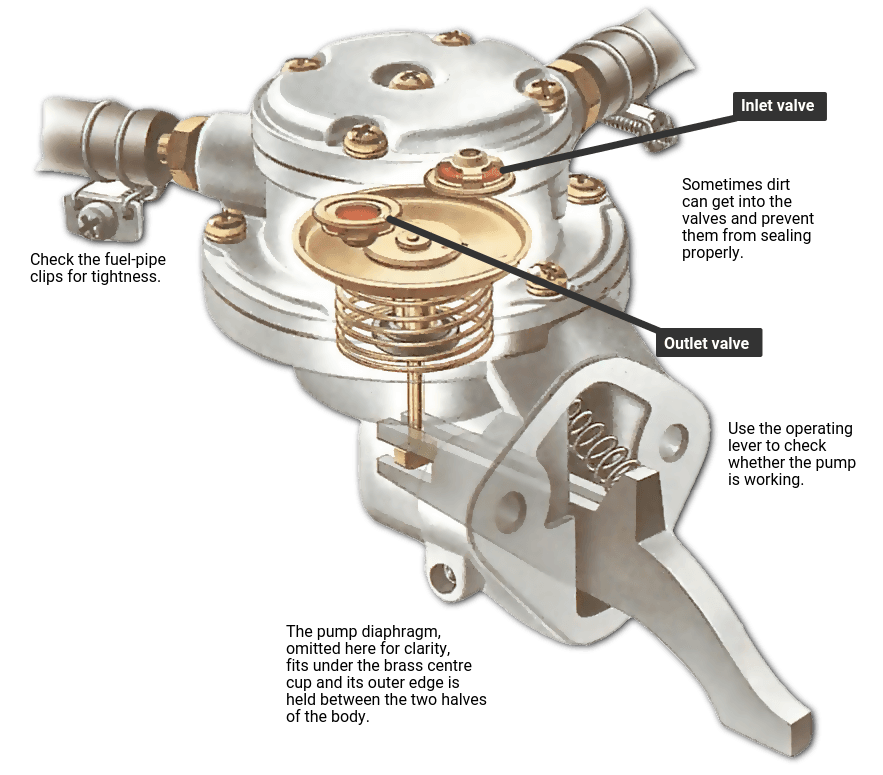
A conventional mechanical fuel pump for a carbureted engine uses engine motion to operate a diaphragm. Changing the chamber volume draws fuel through an inlet valve and delivers it through an outlet valve. The valves direct the flow, while the drive and spring arrangement produce the pumping cycle.
That description applies to a familiar low-pressure diaphragm design, not to every pump driven by an engine. Diesel injection pumps and modern high-pressure gasoline pumps can also be mechanically driven, but their construction and control are different.
This guide explains the basic diaphragm system, how fuel demand interacts with it and why a running engine does not prove every part of the fuel supply is healthy. It is an operating explanation rather than a rebuild procedure or a source of universal pressure specifications.
Credit: www.howacarworks.com
Follow the energy path from the engine to the fuel
The engine supplies motion through the pump's specified drive arrangement. Depending on the application, a lever or pushrod interacts with an eccentric or another designed driving feature. The movement is transferred to the diaphragm assembly. This is why installation geometry matters: a pump can be bolted to the engine yet be incorrectly engaged with its drive. The mounting location is not merely a convenient place to attach a self-powered electric device.
The diaphragm forms a moving wall of the pumping chamber. When chamber volume increases, pressure inside it falls relative to the fuel supply. Fuel can then move through the inlet path as the inlet valve permits. When chamber volume decreases during the delivery part of the cycle, fuel moves toward the outlet. The exact direction in which the diaphragm appears to move depends on how the pump is drawn or mounted, so understanding the volume change is more useful than memorizing up or down from a diagram.
One-way valves make the alternating motion produce net flow. Without directional control, moving the diaphragm could simply push fuel back and forth between the same spaces. The inlet and outlet valves respond to the pressure differences across them. Their sealing and movement matter to delivery. Dirt, damage or incorrect assembly can interfere with that function even if the diaphragm still moves.
This explains why a pump's mechanical motion alone does not prove that it supplies the required fuel. The spring and linkage arrangement is also part of the design. Holley: application-specific mechanical diaphragm and spring assembly lists a diaphragm-and-spring assembly for specific pump applications, and its Holley: mechanical fuel pump servicing instructions documents a supported servicing arrangement. These examples show why internal parts are not generic pieces of rubber and wire. Spring characteristics, diaphragm shape and linkage geometry must match the pump.
A visually similar replacement can alter operation or fail to assemble correctly. In a common demand-responsive diaphragm design, the spring contributes to fuel delivery while the linkage accommodates the relationship between engine motion and downstream demand. When the carburetor's inlet control restricts further fuel entry, the pump does not simply force unlimited additional fuel into the bowl. The exact operating mechanism and specified pressure depend on the pump. Do not generalize that explanation into a claim that every mechanical pump needs no external regulation under every installation.
The carburetor and pump perform different functions. The pump supplies fuel to the carburetor; the carburetor manages its own fuel level and metering through its design. A flooding carburetor can involve an inlet-control or pressure problem, while an empty bowl can involve supply, pump or carburetor issues. Neither observation identifies the pump by itself. Understanding the division of functions helps avoid replacing the pump for every rich or lean running complaint.
Pump pressure and flow are related but different measurements. Pressure describes the force per area in the circuit, while flow describes how much fuel is delivered over time. A system can show a pressure result under one condition yet fail to provide sufficient delivery under another. Manufacturer ratings must be read with their stated conditions. A free-flow figure is not automatically the delivery available against the pressure and restrictions of an installed system.
Engine speed affects how frequently the drive operates, but the complete delivery result depends on more than speed. Fuel supply, valves, diaphragm condition, drive movement and downstream demand all matter. A pump that appears adequate at idle may not meet the required condition elsewhere. Conversely, poor high-load operation can involve a restriction before the pump rather than a worn diaphragm. The correct diagnostic procedure determines which measurement separates those possibilities.
Understand the surrounding system and common misconceptions
The pump relies on a usable inlet supply. A restricted pickup, unsuitable filter, damaged hose or air-entry problem can prevent normal delivery. Because the pump is part of a system, a low output result needs interpretation alongside those conditions. Replacing the pump without checking its supply can leave the same complaint. The physical principle is straightforward: the pump cannot deliver normal fuel flow when its inlet path is not providing the required fuel under the intended conditions. The drive side can also be at fault.
An incorrectly positioned lever, unsuitable pushrod arrangement or application mismatch may limit the pumping action. These are vehicle-specific installation questions. Do not use the mounting bolts to force a pump into an uncertain position, and do not borrow a drive-installation trick from a different engine. The proper manual identifies how the pump engages and how that engagement is checked. A diaphragm can be damaged, but similar symptoms can arise from valves, supply restrictions or the carburetor. A leak needs localization because fuel from a fitting can travel across the housing.
If fuel is appearing where it should not, stop engine operation and investigate. Do not assume that a pump is safe because it still delivers enough fuel to keep the engine running. Sealing and delivery are separate requirements. Mechanical does not mean maintenance-free or rebuildable. Some pumps have manufacturer-supported service kits; others are replaced as assemblies. The presence of screws does not establish that a rebuild procedure is available.
Holley's service documentation applies to its identified products and must not be used to justify opening an unrelated sealed pump. The correct part number is essential before choosing repair components or deciding whether internal service is appropriate. A pulse-operated small-engine pump uses pressure changes rather than a direct engine lever to move its diaphragm. Briggs & Stratton: pulse-operated fuel pumps explains that arrangement. The underlying chamber-and-valve principle is related, but the drive source and troubleshooting are different. A damaged pulse hose can matter in that system, whereas a directly driven automotive pump has a different operating connection.
Keeping these designs separate prevents misleading instructions about vacuum hoses on a pump that has none. A high-pressure injection pump is another separate category. It may receive mechanical drive from the engine, but that fact does not make this low-pressure carburetor explanation its service guide. High-pressure fuel systems require dedicated procedures, equipment and cleanliness controls. Never loosen an injection line to demonstrate pumping action. The term mechanical describes the energy source broadly; it does not establish the pressure range or safe test method.
An electric pump conversion changes the system design. It is not simply a matter of replacing engine motion with a motor anywhere in the line. The required pressure, regulation, fuel compatibility, mounting and shutdown controls need to be addressed. A pump advertised with a larger flow number is not automatically a better replacement for a carbureted vehicle. The correct installation must meet the engine and fuel-system requirements as a whole.
Likewise, an auxiliary electric pump should not be added merely because a mechanical pump seems slow to fill a serviced system. First establish the cause of the starting or supply problem. A second pump can alter inlet conditions and introduce new control requirements. The fact that the engine starts afterward does not prove that the original defect has been safely repaired. Use an approved design when a conversion is actually intended.

Credit: www.youtube.com
Use the explanation to ask better diagnostic questions
If a mechanical-pump problem is suspected, identify the engine and pump before testing. Obtain the specified pressure and delivery procedure, including safe fuel handling and ignition precautions. Ask whether the inlet supply, drive and downstream system were considered. A useful diagnosis separates inadequate drive, poor valve or diaphragm performance and an external restriction rather than treating all of them as the same failure. For a replacement, verify the exact application and any pressure-regulation requirements. Keep the supplied instructions and use the correct seals and fittings.
After installation, check for leakage and confirm the specified operating result. A pump that fits the mounting holes has not necessarily passed the compatibility or performance checks. The completed system must both supply fuel correctly and remain sealed. The essential operating model is a driven flexible chamber with directional valves, working within a particular fuel-supply and demand arrangement. That model explains why the pump can move fuel without an electric motor, why valve and diaphragm condition matter, and why symptoms still need testing. It is most useful when it prevents an assumption: motion is not the same as verified delivery, and the label mechanical is not a substitute for the correct application-specific procedure.


Automotive reference information. Confirm specifications in the manual for your exact vehicle. Original replacement guides link to their research sources. About us