A car may have one fuel pump, more than one pumping stage or a system whose parts are counted differently by owners and parts catalogs. There is no reliable single number for every car. A conventional port-injected gasoline vehicle often has a tank supply pump, while a direct-injection system may also use an engine-driven high-pressure pump. Some tank layouts add transfer devices, and some performance applications use multiple electric pumps. The correct answer comes from the exact vehicle's fuel-system diagram.
Before counting, decide what you mean by pump. An electric motor that supplies the engine, a high-pressure injection pump and a suction-jet transfer device perform different jobs. A fuel-level sender measures fuel quantity and is not necessarily another powered pump. A complete module can combine several components inside one service part. Counting visible covers or catalog entries without identifying their functions can therefore produce a misleading answer.
For an owner buying a replacement, the practical question is usually not how many pumps exist, but which assembly has failed and which part fits the vehicle. Record the year, engine, fuel type, market and vehicle identification. Include modifications, especially an aftermarket tank or fuel system. A diagram for another engine option may look familiar while describing a different arrangement. Use the count as a way to understand the system, not as a shortcut around part identification.

Credit: www.cars.com
Count functions and flow paths rather than covers
Begin at the tank and trace the fuel route toward the engine. Identify the pickup, the supply pumping stage, filters, control or regulation components and the injection system. Then trace any return or transfer route shown in the diagram. This exercise often explains why two components both appear in a fuel-pump search even though they serve different purposes. Keep separate notes for location, function and service-part name rather than assuming those labels are interchangeable. An in-tank module can contain the pump motor, a reservoir, a strainer and a level-sensing arrangement. The supplier may sell the whole module even if the motor is the suspected fault. That does not mean every item within the module is a separate pump. Conversely, replacing only a motor may be inappropriate where the approved service part is the complete assembly.
The service procedure and parts listing determine the repair scope, not the owner's preferred way of counting components. A high-pressure stage serves a different requirement from the tank supply stage. When a system uses both, low supply delivery can affect the high-pressure side. A pressure complaint at the engine does not automatically identify the engine-driven pump as the failed part. Ask which stage was measured and whether the upstream supply met its specification. The architecture explains the diagnostic sequence; it is not just a fact to memorize about the vehicle. Some tanks have more than one chamber or a shape that requires fuel to be moved toward the pickup. A transfer arrangement may use a jet or siphon principle rather than an additional electric motor. Its presence can be important when a vehicle behaves as though it is out of fuel despite fuel remaining elsewhere in the tank.
Identifying that device requires the tank diagram. A second access cover by itself does not establish a second electrically driven supply pump. Parts catalogs can use broad names that hide these distinctions. Mopar: 2014 Charger Pursuit 5.7L fuel module catalog provides a concrete example: the selected catalog includes a primary module and auxiliary entries whose descriptions refer to pickup and level-unit components. That is a reason to examine the detailed description and vehicle applicability, not to infer a universal Charger pump count from a heading. The same discipline applies to Chrysler 300 or other related models. Platform relationships do not replace a vehicle-specific lookup. Electrical diagrams help distinguish motors from sensors. A level sender circuit does not prove that its assembly contains an independently powered pump.
A pump-controller circuit may feed a motor through a control module rather than a simple relay. Reading the circuit description alongside the mechanical diagram is more informative than counting connector pins. Do not probe an unidentified connector or apply battery power to determine what it does; incorrect assumptions can damage electronics or create a fuel hazard. Mechanical pumps add another variation. Carter: mechanical pump guide, archived manufacturer instructions describes application-specific engine-driven designs, often associated with carbureted systems. An older vehicle may have one such supply pump, but a modified vehicle could have a different arrangement. The registration year alone does not prove that the original engine or fuel system is still installed. If the vehicle has been restored, converted or modified, compare the actual hardware with the documentation supplied for that work. Diesel systems require particularly careful terminology.
Lift pump, transfer pump and injection pump can refer to distinct functions, and engine families differ. An oil pump used to operate an injection mechanism is not a fuel pump merely because its operation affects injection. Likewise, a diesel exhaust fluid pump serves an emissions-fluid system rather than the engine's fuel supply. A count that mixes these components is not useful for diagnosing a fuel-delivery complaint. The number of cylinders does not determine the number of fuel pumps. Two cylinder banks do not automatically require two tank pumps. A high-output engine may need a different system from a lower-output version, but that has to be confirmed from its specification. Avoid rules such as every V8 has two pumps or every modern car has one. These shortcuts can lead to ordering the wrong part or overlooking the stage that actually needs testing.
Electric vehicles introduce a basic boundary: a battery-electric vehicle does not need a gasoline or diesel fuel-delivery pump. A hybrid with a combustion engine does have a fuel system, but its engine-start and isolation behavior may differ from a conventional car. Do not use silence at rest to count or diagnose its pumps. The vehicle can command components according to operating conditions that are not obvious from whether the driver hears an engine running. Motorservice: electric fuel pump designs and damage analysis gives manufacturer background on different electric pump arrangements and failure mechanisms. Use that kind of technical reference to understand the functions, then use the vehicle service information for the actual layout. A general diagram can explain a principle without proving that your car has that design. Maintaining that separation prevents a helpful illustration from becoming an incorrect repair instruction. For a purchase, make a short identification sheet.
Record the vehicle identification, engine code where available, tank configuration, required assembly name and the verified part number. Add any build-date restriction or superseded number shown by the supplier. If a catalog offers left and right assemblies, determine what each does before selecting one. If the listing remains ambiguous, ask the supplier to verify the part against the vehicle rather than choosing the cheaper photograph. For diagnosis, add the symptom and the test evidence. A failed level reading points toward a different investigation from inadequate fuel delivery, even when both functions share a housing. A pump count does not tell you which part caused a no-start. Ask whether the relevant stage receives the correct command and supply and whether its output meets the specified requirement. This keeps the architecture connected to a decision rather than to unnecessary parts replacement.
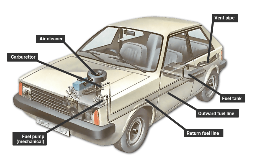
Credit: www.howacarworks.com
Turn the diagram into a clear answer for your vehicle
A useful answer sounds like this: this exact vehicle has a tank supply stage and a separate engine high-pressure stage, with the listed part responsible for the measured failure. Another vehicle may have a single supply pump and an auxiliary level or transfer assembly. These descriptions communicate function and location more clearly than simply saying one or two. They also allow a technician or supplier to correct a misunderstanding before parts are ordered. Avoid dismantling the tank merely to count components. Documentation and verified parts identification should normally answer the architecture question without introducing fuel exposure or disturbing seals. Physical inspection is justified by a service task, not curiosity about the number alone. If two sources disagree, compare what each is counting and which version each describes. One may count powered motors while another counts complete modules. One may cover an earlier model year or a different engine. Resolve those differences using the vehicle identification and the manufacturer's diagram.
Do not average the answers or assume that the most confident forum comment applies. A discrepancy is a prompt to refine identification. After replacement, retain the part details and any approved changes. If a module design has been superseded or its connector updated, that record will help future diagnosis. Check the original complaint, fuel-level indication where relevant and leakage according to the service procedure. Installing the correct number of parts is not the objective; restoring the correct function is. The reliable approach is therefore to define the component, trace its role and verify its application. Count supply pumps, high-pressure stages and transfer devices separately. Keep sender units and unrelated fluid pumps out of the total unless you explicitly explain why they are being discussed. That method produces an answer that helps with maintenance, diagnosis and purchasing without pretending that every car shares the same fuel system.


Automotive reference information. Confirm specifications in the manual for your exact vehicle. Original replacement guides link to their research sources. About us