A fuel pump needs the voltage and control signal specified for its design and operating condition. On a vehicle with a nominal 12-volt electrical system, that does not mean every measurement at the pump must read exactly 12.0 volts. Charging voltage, cranking conditions, wiring losses and electronic speed control can all affect the reading. Some pumps are controlled with a switched waveform, and some systems use different motor or controller arrangements. The correct target comes from the vehicle service information and the pump's specification.
The important diagnostic question is whether the pump receives the intended supply while doing its required work. A voltage reading at an unplugged connector does not answer that fully. A circuit with excessive resistance may show a plausible voltage without a load and then lose voltage when the pump operates. Conversely, a lower average reading on a deliberately controlled circuit may be normal. Interpret the number only after identifying how the circuit works.
Do not apply extra voltage to make an underperforming pump run faster. That can damage the pump or its controller and bypass the intended protection. This guide explains how to make sense of voltage evidence and what to ask a technician. It does not provide a universal minimum, a wiring jumper recipe or permission to energize an unidentified terminal.
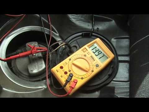
Credit: www.youtube.com
Interpret the number in the correct operating state
Begin with the vehicle identification and circuit diagram. Determine whether the pump receives a conventional relay-switched supply or a controller-managed output. Identify the power and ground paths and any separate command or feedback wires. A connector may also include level-sender circuits that must not receive test power. Wire color, terminal size and the number of pins are not adequate substitutes for the diagram. Nominal system voltage is a label for the electrical architecture, not a guarantee of a fixed measurement. Battery condition and charging operation affect the available voltage. A reading taken with the engine off should not automatically be compared with one taken while charging. Record the battery measurement and pump operating state at the same time as the pump reading.
Without that context, a number written on a work order may be impossible to interpret later. The pump may operate only during a limited command window in a particular test state. An apparent zero after that window can be different from a failure to receive voltage when commanded. The exact prime and run strategy varies, so do not assume every car follows the same ignition-on timing. A scan tool or manufacturer test procedure may be required to establish a controlled command state. Repeatedly cycling the key without understanding the strategy can confuse the result. Delphi: performing a fuel-pump voltage-drop test explains why loaded voltage-drop testing matters when pump performance is low. A supply or ground connection can consume part of the available voltage through unwanted resistance. The pump then operates under different conditions from those assumed by the performance specification.
Correcting that circuit problem may restore delivery without replacing the pump. The test should therefore examine the electrical path as well as the component at its end. Voltage drop is a measurement across a section of a working circuit. It is not the same as measuring the pump terminal relative to any convenient piece of body metal. The choice of reference points determines what part of the circuit is being assessed. A technician can divide the power and ground paths into sections to locate excessive loss. The allowable value and test conditions must come from the applicable diagnostic procedure rather than a universal internet threshold. Consider an illustrative calculation, not a pass/fail standard. If a conventional loaded circuit has 13.6 volts available at its source and the measured loss across its combined supply and return paths is 1.0 volt, the motor does not receive the full source voltage.
The arithmetic helps explain the relationship, but it does not establish which connection is defective or whether those conditions match the vehicle's specification. Diagnosis still requires locating the loss and comparing it with the correct limits. An unloaded test can conceal that loss because little current is flowing through the resistance. This is why a meter may display a reassuring number at a disconnected plug even when the connection cannot support the pump. The correct response is not to dismiss the meter, but to use the appropriate loaded test. Test adapters must preserve the connector and circuit safely. Forcing ordinary probes into terminal cavities can damage the contacts and introduce the very fault being investigated. A controlled pump introduces another complication. Pulse-width modulation switches the supply in a pattern to manage output, so a basic meter may report an average that differs from the waveform's high level.
The meter's response also matters. Do not treat every average below battery voltage as a bad wire. Identify the control strategy and use the specified measurement method, which may involve duty-cycle information, scan data or a scope. A controller's command value is not necessarily the same as measured pump output. Requested duty cycle, reported module output and a meter reading represent different observations. A useful diagnostic record names each parameter and where it was measured. If the readings disagree, the next check should resolve whether the issue lies in the command, controller, wiring, measurement method or load. Simply replacing whichever part has the word pump in its name skips that reasoning. Pump performance also depends on pressure and flow requirements.
Aeromotive TB-501: selecting a fuel pump explains that available voltage is one of the conditions used when evaluating a pump's flow capability. A catalog flow figure measured at one voltage should not be assumed to apply unchanged at another. That does not justify increasing voltage beyond the approved design. It means the pump and electrical system must be evaluated together under the intended operating conditions. Current provides additional context but is not interchangeable with voltage. A circuit can have supply voltage present while a motor does not draw the expected current, or it can suffer a voltage loss while carrying load. Delphi: fuel pump current waveform testing discusses current-waveform investigation for pump faults. The appropriate test depends on the question being answered.
A current reading without pressure, command state or the correct specification is another isolated number rather than a complete diagnosis. Do not use a fuse rating as the pump's expected current or voltage requirement. The fuse protects a circuit according to its design. Replacing it with a larger one does not improve a weak supply safely. If the correct fuse opens, investigate the cause. If a relay or connector becomes hot, assess the connection and circuit rather than repeatedly changing the fuse. Protective devices should remain as specified while the underlying fault is diagnosed. After recent pump or controller replacement, verify the part and any required installation procedure.
Some modules may require configuration or programming for the particular application, while others do not. The answer must come from that part's service information. A generic claim that every driver module needs programming is as unreliable as saying none do. Connector updates and wiring repairs also need the supplied pin mapping, not a color-to-color assumption. A practical request to a workshop is to document battery voltage, pump command, loaded supply and return measurements, and the relevant delivery result. This creates a record that connects electrical conditions with actual performance. It is much more useful than being told the pump has twelve volts. If the complaint is intermittent, ask whether the measurements were captured during the failure or only while the system was behaving normally.

Credit: www.amazon.com
Use the result to choose the repair
If excessive circuit loss is demonstrated, repair the identified connection or wiring fault using the approved method and retest. If command is absent, investigate why the control system is not requesting operation rather than feeding the pump permanently from another source. If command and supply are correct but delivery remains inadequate, continue with the fuel-system diagnostic procedure. These branches keep the repair tied to evidence instead of to a preferred component. A measurement record should state its units and instrument setting.
A duty-cycle percentage, an average voltage and a peak waveform voltage cannot be compared as if they were the same value. Naming the reading avoids a surprisingly common communication error between the person testing and the person reviewing the result. After repair, repeat the same measurement under comparable conditions. A before-and-after comparison is meaningful only if the pump is operating in the same intended state. Also verify the original starting or running complaint.
An improved voltage number is useful, but the vehicle must still meet its delivery and operating requirements without leaks or new faults. Keep the findings and any wiring-repair details with the service record. For an owner, the concise answer is therefore to use the specified voltage for the actual pump and test state, not a single universal number. A nominal 12-volt label, an average meter display and the voltage delivered to a loaded motor are related but different ideas. Understanding that distinction helps you recognize a sound diagnosis and avoid unnecessary replacement of a pump that was being supplied incorrectly.


Automotive reference information. Confirm specifications in the manual for your exact vehicle. Original replacement guides link to their research sources. About us