To connect a small-engine vacuum fuel pump, first identify the fuel inlet, the fuel outlet and the engine pulse connection from the exact pump and engine documentation. Connect each only to its specified route, using the required hose, clamps and mounting arrangement. Do not identify ports by their position in a photograph. Similar-looking pumps can place the connections differently, and a pulse port is not a spare fuel port.
The term vacuum fuel pump usually refers here to a diaphragm pump driven by engine pressure changes. It is not the same as a vehicle's brake vacuum pump, an electric tank pump or a direct-injection high-pressure pump. If you are working on an automobile and do not recognize the system, verify its identity before following a small-engine guide. The correct connection map depends on the actual equipment, not on the wording of an online listing.
This article is a planning and verification guide rather than a universal hose diagram. It explains what each connection must be confirmed to do and when an installation needs professional help. If the existing hoses have already been removed without labels, pause and obtain the parts drawing. Guessing and then trying the engine can turn a simple connection error into a fuel leak or an engine problem.

Credit: www.youtube.com
Build a verified connection map before fitting the pump
Begin with the engine model, type or specification code and the pump's part number. Photograph any legible marks. Check whether the replacement is explicitly listed for that engine and installation. A pump that has three nipples and fits the mounting holes is not necessarily interchangeable. The supplier should be able to confirm the correct application and provide port identification. If it cannot, do not treat the absence of information as permission to experiment. Briggs & Stratton: pulse fuel pump operation and service explains that these pumps use engine pressure changes and gives manufacturer guidance for their connections and service. The important installation lesson is that the pulse source is part of the engine design. Use the specified source and hose route. Do not substitute an available intake nipple, crankcase breather opening or other fitting simply because it appears to produce suction.
The required signal and the surrounding plumbing need to match the intended arrangement. Mark the verified fuel inlet on a sketch. Trace its route back toward the tank, including any shutoff valve and filter shown in the equipment documentation. Inspect that route with the engine stopped and cool. Look for damaged hose, unsupported bends and rubbing points. A new pump cannot compensate for an obstructed inlet or a hose that admits air. Correct obvious supply-path defects using suitable replacement parts before judging the pump's performance. Mark the fuel outlet and trace it to the specified carburetor connection. Do not confuse a carburetor vent or overflow connection with its fuel inlet. If the receiving connection is unclear, use the carburetor diagram as well as the pump diagram.
A hose can fit over the wrong nipple convincingly. Physical fit is therefore only a final compatibility check after function has been established, not the method of identifying the route. Mark the pulse connection separately, preferably with a different label on the sketch. Its job is to transmit the engine's operating signal to the pump. It should not be routed through a fuel filter or joined to the fuel outlet. Inspect its length, attachment and condition against the specified installation. A crack or loose connection can weaken the signal even when no liquid fuel escapes, so a dry exterior does not prove the line is sound. If fuel is present in a line that should carry only the pressure signal, stop and investigate. That finding can indicate an internal fault or a misconnection, depending on the installation. Do not route the line elsewhere to dispose of the fuel and continue running.
Check the engine manufacturer's instructions for any associated inspection, including lubrication-system concerns where applicable. Correcting the visible hose connection alone may not address the consequences of the original fault. Choose hoses by their required function and specification. The fuel hoses must be suitable for the fuel and conditions in that equipment, while the pulse hose must meet its own application requirements. Do not substitute clear tubing from an unrelated household project because it makes flow visible. Confirm the specified diameter and clamp style. A hose forced onto a nipple or a clamp tightened until the plastic distorts can create a new leak. Mount the pump as specified, preserving the intended position and clearance. Do not leave it hanging from the hoses.
Its location affects routing, vibration exposure and proximity to heat. If the equipment has been modified or the tank relocated, the original pump application may no longer describe the installation adequately. Ask the manufacturer or a qualified installer to confirm suitability rather than assuming a longer inlet hose is the only change needed. Prepare the work area before opening fuel connections. Use the documented shutoff or draining method, suitable containment and control of ignition sources. Prevent accidental engine starting according to the equipment's instructions. Fuel retained in hoses can spill even after a tank valve is closed. Work on cool equipment and keep fuel away from exhaust components, electrical sparks and indoor living spaces. If safe access or containment cannot be arranged, have the installation performed professionally.
During assembly, keep dirt out of the open connections. Cap or protect disconnected lines with appropriate materials. Do not use loose cloth fragments as internal plugs or apply sealant to hose barbs unless the manufacturer specifically requires a product there. Debris introduced during a careful-looking repair can interfere with the system later. Compare each connection with the verified map before securing the final routing, and make sure a clamp has not been forgotten behind another component. Check that the hoses are not kinked when covers and guards return to their normal positions. A route that looks clear with a cover removed may become pinched after reassembly. Keep hoses away from moving linkages, sharp edges and hot surfaces. Refit the specified clips and supports rather than relying on a new route that merely seems shorter.
The goal is to restore the designed path, including the protection provided by surrounding hardware. Before starting, perform a deliberate connection review. Read each label aloud or check it against a written list: tank route to inlet, outlet to the correct receiver, pulse port to the specified engine source. Confirm clamps, mounting and hose clearance. A second person can compare the drawing with the installation without relying on the installer's memory. This is particularly useful after replacing a pump whose port positions differ from the old unit. Do not add a relay, electrical feed or primer device to make this installation work unless an approved conversion design specifically calls for it. Carter: mechanical pump guide, archived manufacturer instructions describes a different family of mechanically actuated pumps, illustrating why shared words such as diaphragm or mechanical do not make procedures interchangeable. If the replacement requires a different operating method, resolve the compatibility issue instead of adding improvised components to compensate.
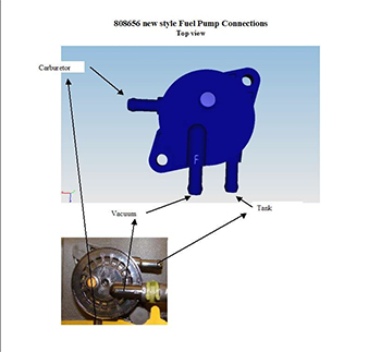
Credit: www.briggsandstratton.com
Verify delivery without turning a connection check into a hazard
Follow the engine manufacturer's restart and inspection procedure. Watch for leakage and stop immediately if a connection leaks or fuel appears where it should not. Do not tighten or rearrange hoses around a running engine. A successful start is encouraging, but check that guards are fitted and that the engine operates normally under the conditions specified for the equipment. The installation is not complete merely because fuel has reached the carburetor once. If the engine still does not receive fuel, return to the verified map and the supply route. Confirm the tank contains suitable fuel, any shutoff is in the required position and the pulse line is intact. Then use the specified diagnostic procedure or a qualified technician. Reversing hoses one at a time until something changes is not troubleshooting. It introduces new configurations without establishing what the correct one should have been. Do not perform a mouth-suction test or pressurize the tank with shop air.
Those shortcuts create exposure and equipment risks and do not reproduce a controlled manufacturer test. A service procedure may specify a delivery check with particular tools and containment, but its details should be followed exactly. If those requirements are unavailable, the useful next action is obtaining the correct information, not improvising a similar-looking test. If a hose is too short after fitting the verified replacement, do not stretch it until the connection is under tension. Recheck the approved routing and required hose specification. A connection that remains attached while stationary can still be stressed by vibration or movement during normal operation. Keep the pump part number, source of the connection diagram and photographs of the completed routing. Future maintenance is easier when the installation can be identified rather than reconstructed from memory. The central skill in hooking up this pump is accurate identification: every hose must have a known function and destination. Once that is established, suitable parts, clean assembly and deliberate verification turn the diagram into a dependable installation.


Automotive reference information. Confirm specifications in the manual for your exact vehicle. Original replacement guides link to their research sources. About us