On a pushrod-operated mechanical fuel pump, the rod must be positioned so the pump lever engages it correctly during installation. The appropriate temporary holding method comes from the engine and pump instructions. Some manufacturer instructions describe using a small amount of specified grease or petroleum jelly on the rod after positioning it correctly. That is an application-specific assembly aid, not permission to pack the opening with grease or insert an arbitrary bolt into the engine block. The key problem is engagement, not merely preventing the rod from falling.
A rod held in the wrong position can still leave the pump lever incorrectly installed. Tightening mounting bolts to force the pump into place can damage parts. Before proceeding, verify that the engine actually uses this pushrod arrangement and that the replacement pump is correct. Many pumps use different drive methods, and an electric fuel pump has no comparable installation rod.
This guide explains how to evaluate the job and avoid common assembly mistakes. It does not provide a universal retaining-bolt length, torque setting or crankshaft position. Those details depend on the engine and its hardware. If the original procedure is missing or the rod is damaged, obtain the correct service information before trying a workaround that may create a more expensive repair.

Credit: www.youtube.com
Position the drive correctly before choosing a holding method
Identify the engine rather than relying only on the vehicle model. Older vehicles may have replacement engines, changed blocks or aftermarket pumps. Record the engine identification and the new pump's part number. Compare the pump's mounting and operating lever with the specified application. A similar-looking pump can have different geometry. The fact that its mounting holes align does not prove that its lever will work with the existing rod and drive. Carter mechanical pump installation instructions, archived by Dalhems describes a GM pushrod installation and emphasizes correct rod position and lever contact. The document is a manufacturer instruction sheet hosted by a parts supplier; its applicability must be checked against the pump being installed.
It is useful evidence that proper engagement comes before bolt tightening. It is not a universal procedure for every mechanical pump, marine application or modified engine. Prepare the vehicle for the job using the relevant fuel and engine safety instructions. Work on a cool engine, prevent accidental starting and handle residual fuel with suitable containment. The pump opening is not an appropriate place to work while someone may operate the starter. If the crankshaft has to be repositioned, follow the engine's manual rotation procedure and all associated precautions. Do not put fingers into a drive opening while another person turns the engine.
Remove the old pump and associated parts as specified, retaining their identity and orientation for comparison. Inspect the rod and the contact surfaces for damage according to the manual. A worn or bent rod is not repaired by holding it more firmly. Likewise, a replacement pump should not be used to compensate for a drive problem elsewhere. If the rod does not move as expected, investigate the obstruction or damage instead of forcing it farther into the bore. Correct engine position can reduce the load presented to the pump lever during assembly. The service instructions determine how to achieve that position.
Do not use a generic crankshaft angle taken from an unrelated engine. The point is to place the drive in the condition specified for installation, then maintain the rod's location long enough to engage the pump. A holding aid is secondary to that initial positioning. Where the applicable manufacturer instructions allow grease or petroleum jelly as a temporary aid, use the stated material and amount. More is not necessarily better. Excess material can obscure the contact area and introduce unnecessary contamination. Do not substitute adhesive, threadlocker or a hardening sealant to glue the rod in place.
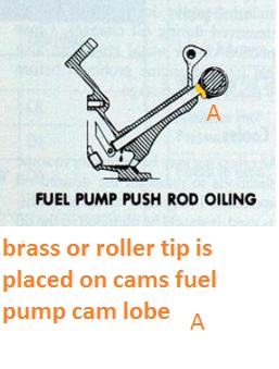
The rod must operate normally after assembly; a temporary installation aid must not become a permanent obstruction. Some workshop discussions describe using a bolt in a nearby threaded opening to retain the rod. Do not assume your engine has the same passage, thread or safe engagement depth. An incorrect bolt can damage or trap the rod, and forgetting a temporary retainer can prevent normal operation. Use such a method only if the exact engine's service procedure authorizes it and specifies the hardware and removal step. This article intentionally does not supply a guessed bolt length. Keep a written note of any temporary tool or retainer used.
Before closing the job, account for it explicitly. This simple practice is especially helpful when the installation is interrupted or another person assists. A temporary item that becomes invisible after the pump is fitted is easy to overlook. The checklist should distinguish parts that remain installed from tools or holding devices that must be removed before the engine turns. Position the pump lever as the verified instructions require. Delphi mechanical fuel pump installation sheet, distributor-hosted copy warns about incorrect lever placement on pushrod-driven installations and shows the importance of engagement. Do not generalize a diagram without checking which way it is viewed.
If the pump cannot be positioned with the expected fit and spring resistance, stop and compare the components again. Mounting bolts should secure a correctly located assembly, not force mismatched parts into apparent alignment. Inspect the gasket and mounting surfaces according to the installation sheet. Use the correct gasket and any specified mounting plate. Do not add layers to solve an unexplained gap or use excess sealant to compensate for a poor fit. Changing the spacing can affect the relationship between the drive and the pump. Keep oil passages and other required openings clear, and replace damaged hardware with the specified parts rather than whatever bolts happen to fit.
Start and tighten fasteners only as the service instructions direct, using the correct torque where specified. Alternate or staged tightening requirements must come from the applicable document. If tightening pulls the pump into an unexpected bind, stop. Continuing until the flange is flush can conceal an engagement error instead of correcting it. Recheck rod location, lever position, part identity and gasket arrangement before applying further force. Fuel-line reconnection needs equal care. Align fittings without twisting or stressing the lines, use the correct seals and follow the specified connection method.
A successful pushrod installation does not make a damaged hose or fitting acceptable. Do not use the fuel lines to pull the pump into position. If a replacement's ports require an approved orientation adjustment, follow its instructions rather than rotating or loosening parts arbitrarily. Carter: mechanical pump guide, archived manufacturer instructions describes several mechanical pump families, reinforcing that the drive and construction are application-specific. Some designs can be serviced in ways that others cannot. A photograph of another owner's installation may clarify what to look for, but it cannot establish the correct dimensions or materials for your engine. The pump manufacturer's instructions and engine service information should agree before the assembly is put into operation.
Credit: garage.grumpysperformance.com
Verify the assembly before and after the first start
Before restoring the vehicle to operation, confirm that all temporary holding devices have been removed or handled as specified, the fasteners are correctly tightened and the fuel connections are secure. Check that tools and loose materials are clear of belts and other moving parts. Review the installation steps rather than relying on memory. If the job was interrupted, repeat the check from the written list before attempting to start the engine. Consider why the old pump failed. If its diaphragm leaked fuel into an engine area where contamination is possible, follow the required inspection and oil-service instructions before running. A new pump does not reverse damage or contamination left by the old one. If the previous pump did not deliver fuel, the drive, inlet supply and other relevant causes should have been evaluated rather than assuming that replacement alone resolves the complaint. Use the specified startup and leak-check procedure. Stop immediately for leakage or abnormal mechanical behavior. If delivery is still inadequate, do not keep cranking to persuade the pump to work.
Recheck the installation and obtain the appropriate diagnostic measurements. An engine that starts briefly is not proof that the lever and rod relationship is correct under all conditions, especially if there are unusual noises or continuing delivery problems. If the old and new operating levers differ visibly, pause even when the catalog suggests the part is correct. A superseded design may be legitimate, but the supplier should explain the difference and confirm the application. Do not bend a lever or shorten a rod to make the parts resemble each other. Altering the drive geometry without an approved specification removes the basis for knowing whether the pump will operate correctly after assembly. Keep the part number, installation document and any findings about rod wear with the service record. The durable result is not simply a rod that stayed up long enough to install the bolts. It is a correctly matched, correctly engaged drive that operates freely and supplies fuel without leaks. Temporary retention is only one small step within that larger verification.


Automotive reference information. Confirm specifications in the manual for your exact vehicle. Original replacement guides link to their research sources. About us