Remove a fuel-pump relay only after confirming that the vehicle actually has a removable relay, identifying its exact location and following the specified electrical isolation procedure. Where the design uses a plug-in relay, the approved removal tool grips the relay body and withdraws it as directed without damaging the socket. Some vehicles instead use integrated electronics or a pump-control module, so there may be no separate relay to pull out. A fuel-pump label on a diagram does not guarantee the component is owner-serviceable. The reason for removal matters.
Replacing a diagnosed relay, isolating a circuit during service and trying to relieve fuel pressure are different tasks. Removing the relay alone does not prove that pressure has been released. Nor does a no-start after removal confirm that the relay was previously defective. Define the task before acting so the result can be interpreted correctly.
Use the owner's manual and workshop information for the exact model year, engine and market. A fuse-box photograph from a similar vehicle can place the relay in a different cavity or omit a build-date change. If the manual directs relay work to a technician, follow that direction. This guide explains identification and decision points rather than supplying a universal location, terminal bridge or replacement part number.
Credit: www.yourmechanic.com
Identify the component, isolate it and inspect what removal reveals
Start by recording the existing complaint and diagnostic information when it is safe to do so. If the vehicle intermittently fails to start, note the conditions and save fault codes before disconnecting the battery. A relay can be part of the investigation without being the cause. Unplugging components at random may add new codes and make the original problem harder to interpret. The goal is to preserve useful evidence before changing the circuit. Locate the correct power-distribution center or relay panel from the documentation. Some vehicles have several fuse boxes, and a nearby fuel-related fuse may serve a different function from the pump motor. Match the diagram's orientation to the physical box.
A diagram viewed from the underside can be confusing when compared with a top-down photograph. Confirm the cavity designation and component name rather than relying on a remembered position. Determine whether the relay is a separate plug-in part. A printed-circuit-board relay inside a module is not removed by pulling on an external housing. If the service information identifies an integrated unit, do not pry it open or attempt a solder repair based on a generic relay guide. The approved diagnostic and repair path may involve a control module or distribution assembly. Identifying this early prevents damage to an otherwise repairable system. Read the service precautions before touching the box.
Ford owner manual: fuses, relays and service precautions is one example of an owner manual that directs relay and high-current-fuse replacement to an authorized service provider. Its instructions are not universal for other vehicles, but they demonstrate why a generic online procedure should not override the manual. Electrical isolation, retained power and component accessibility vary. Turning the key off may not be the only required preparation. If relay removal is part of a fuel-pressure relief procedure, follow that procedure in its stated order. Some methods require controlled engine operation before final electrical isolation; others use different equipment. Do not invent a sequence by combining steps from several vehicles. Removing the fuel cap or disconnecting the battery does not necessarily relieve delivery pressure.
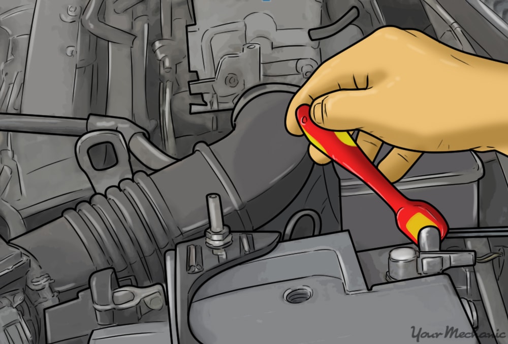
Keep all fuel connections closed until the prescribed pressure-relief process has been completed and the system is ready for service. With the specified safe state established, remove the panel cover carefully and keep dirt and moisture out. Note the relay's orientation and markings before removal. Use the tool and technique appropriate to the relay and space available. Do not insert a metal screwdriver between live or potentially energized terminals, and do not pull on nearby wires to gain leverage. A tight relay or damaged socket is a reason to stop and inspect, not to increase force blindly. Some relay housings have limited room around them, so ordinary pliers may crush the body or slip into adjacent components. A suitable relay puller can provide controlled grip where the design permits it.
Follow the manufacturer's direction for withdrawal and any retaining feature. If the relay will not move without distorting the box, obtain service assistance. Breaking the housing can turn a small replacement into a socket or distribution-center repair. After removal, compare the part markings with the specified replacement. Matching external size or pin count is not enough. Internal contact arrangement, current capacity and suppression components can differ between similar-looking relays. A relay borrowed from another circuit may not be an appropriate test substitute. Do not recommend a swap unless the service information confirms the exact interchangeability and the consequences for the other circuit are understood.
Inspect the removed relay and socket visually. Heat discoloration, melted plastic, corrosion or displaced terminals are evidence requiring further assessment. A new relay in a damaged socket may not correct the connection resistance that caused heating. Conversely, a normal-looking exterior does not prove the contacts are sound. Record what is visible and let the electrical tests determine what cannot be seen. Avoid scraping or bending terminals as an improvised repair. Delphi: performing a fuel-pump voltage-drop test explains why resistance in a pump's electrical supply can reduce performance. That principle is relevant to relay contacts and socket connections, but the actual test must follow the circuit diagram and operating conditions.
A relay click tells you that something moved; it does not establish that the load circuit is delivering adequate power. A technician may need loaded measurements to distinguish a contact problem from a control or downstream fault. Do not bridge socket terminals with a loose wire as the next automatic step. Terminal assignments are not universal, and an incorrect bridge can damage controls or energize a pump unexpectedly. A controlled service test, where specified, uses the correct circuit identification and protective equipment. It is not a permanent bypass. The normal control system may stop fuel delivery under conditions that an improvised bridge ignores. If the fuse also fails, replacing the relay does not explain the overcurrent.
Use the specified fuse type and rating and investigate the circuit fault. Installing a larger fuse to keep the pump running can expose wiring to damage. A relay, fuse and pump are separate components with related functions; none should be selected as the culprit merely because it is easiest to reach. The diagnostic result should identify where the electrical path is failing. When a replacement pump kit includes wiring instructions, read those separately from the relay work. Delphi: in-tank fuel pump replacement instructions notes that some fuel-module applications have connector updates. A relay change cannot compensate for an incorrect connector repair at the tank. If the complaint began after pump replacement, review the complete installation and the documented electrical repair rather than treating the relay as a convenient next guess.

Credit: www.youtube.com
Reinstall correctly and verify the original complaint
Store the removed relay in a labeled bag so it cannot be confused with parts from another circuit during the investigation. Refit only the verified correct part using the specified orientation and seating procedure. Ensure the surrounding components remain in their original positions. Restore the panel cover and its seal so the box is protected from water and debris. Then restore power according to the vehicle instructions. Do not leave the cover off simply because another test may be needed later; environmental protection is part of normal assembly. Check the result against the reason for removal.
If the relay was replaced for a proven contact fault, verify the relevant circuit operation and the original symptom. If it was removed only for isolation, confirm that the vehicle returns to its expected operating state after the main service work is complete. A pump sound alone is not a complete fuel-delivery test, and a single successful start does not settle an intermittent complaint. If the replacement does not correct the complaint, do not repeatedly remove and refit it hoping that the contact will improve. Record whether touching the relay or box changed the symptom, then have the connection and control circuit tested. A temporary response to movement can be valuable evidence of an intermittent fault, but it does not show whether the relay, socket, wiring or nearby component is responsible. Preserve that observation without treating it as a completed repair.
Keep the old part identification, test findings and any socket-repair details with the service record. If heat damage was present, the record should explain how the damaged connection was corrected. If the relay tested correctly and another fault was found, document that too. This prevents a future technician from interpreting repeated relay purchases as evidence that several relays failed. The useful removal process is therefore identification, specified isolation, controlled physical removal, inspection and verified reassembly. The small size of the component does not eliminate the need to understand its circuit. When the relay is integrated, the socket is damaged or the required procedure is unclear, stopping for professional service protects the vehicle and preserves the evidence needed for a proper repair.


Automotive reference information. Confirm specifications in the manual for your exact vehicle. Original replacement guides link to their research sources. About us