Remove a fuel pump lock ring using the tool and release method specified for that tank assembly, after completing the vehicle’s fuel-system safety preparation. Do not assume every retaining ring unscrews in the same way or that a screwdriver and hammer are acceptable substitutes.
The ring retains the module and helps maintain the correct sealing arrangement. Damaging its tabs, the tank neck or the module flange can turn a pump replacement into a fuel or vapor leak. If the ring is badly corroded or will not release with the correct method, stop before increasing force.
Identify the retainer and access arrangement
Check the service diagram for the exact vehicle. Some modules use a rotating locking ring, others a large threaded collar or a different fastening arrangement. The correct removal direction, tool engagement and installation requirement belong to that design.
Establish whether the manufacturer provides a service opening or requires tank removal. Do not cut a new access hole above an installed tank. If the tank must be lowered, use the specified support and removal procedure; the ring operation does not make unsupported tank work safe.
Prepare the system before disturbing the ring
Follow the vehicle instructions for pressure relief, electrical isolation and fuel-level preparation. Removing a filler cap is not a substitute for relieving pressure in a pressurized delivery circuit. Keep ignition sources away and work with suitable ventilation and fuel containment.
Delphi’s in-tank pump installation instructions provide general replacement precautions, but the vehicle procedure determines the details. If fuel lines must be detached, use the correct connector identification and release method rather than pulling them against the retaining ring.
Clean and document the area
Before opening the tank, remove loose contamination around the module using a method suitable for fuel-system work. The aim is to prevent debris from falling into the opening, not to push dirt beneath the flange. Do not use ordinary powered tools or a household vacuum around fuel vapor.
Record the module’s installed orientation and the routing of hoses and wiring. Use factory alignment marks and instructions for reassembly; a photograph is helpful context but does not replace the specified orientation. Keep debris and removed parts away from the sealing surface.
Choose a tool that engages the ring correctly
A proper wrench distributes force through the intended engagement points. Check the tool’s application list and its fit on the actual ring before turning it. A tool that touches only one tab or slips under load can deform the retainer.
Match the wrench to the retainer shown in the vehicle service information and confirm its application before use. Similar tool names do not establish that their engagement points fit the same ring. The ratchet drive size identifies the tool connection, not the tightening torque for the fuel-tank retainer.

Credit: www.reddit.com
Release it according to the service procedure
Apply controlled force in the specified direction with the tool fully seated. Follow any instruction for supporting or depressing the module while releasing the retainer. Do not assume the module will remain stationary when retention is removed; its construction and spring loading vary.
Do not add heat, strike a steel chisel against the ring or reach for an impact tool because the first attempt failed. If tabs begin bending, the tool slips, or the tank neck moves or cracks, stop. Inspect the assembly and obtain the correct repair method instead of turning damage into a larger opening.
A seized or corroded ring changes the repair
Assess the condition of the retainer and tank flange before planning reuse. Corrosion can affect the retaining features as well as the visible ring. A new ring cannot compensate for a damaged tank neck, and additional force cannot restore missing retaining material.

Credit: www.youtube.com
Use only products and techniques permitted for the assembly; keep chemicals out of the tank and away from seals unless their use is explicitly approved. If destructive removal is necessary, that is a workshop repair with a plan to protect or replace affected parts—not a general driveway shortcut.
Refit with the correct seal and orientation
Follow the instructions for seal replacement, seating, lubrication if specified, and ring reuse. Do not add general-purpose sealant to compensate for a damaged or incorrectly seated gasket. Ensure the module is positioned correctly and the sender float is not obstructed during installation.
Tighten or rotate the retainer to the specified torque or lock position for that design. A universal torque value is inappropriate. Confirm that the ring has engaged all the required retaining features; a ring that looks flat from one angle may still be incompletely seated.
Verify before closing the access area
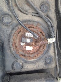
Credit: gmtnation.com
Complete the prescribed priming and leak checks with normal system control restored. Inspect the module seal and reconnected fittings as directed, and check for fuel odor or other signs that require investigation. Do not conceal the area with trim until the required verification is complete.
A vapor-sealing fault may not produce an obvious liquid puddle, so follow any additional leak or evaporative-system checks specified for the repair. For the wider return-to-service sequence, use checks after replacing a fuel pump.


Automotive reference information. Confirm specifications in the manual for your exact vehicle. Original replacement guides link to their research sources. About us