A fuel-pump toggle switch should not simply connect battery power to the pump and replace the vehicle's normal controls. That arrangement can leave fuel flowing after the engine stops and can overload an unsuitable switch or wiring. A safe design must account for the pump load, circuit protection, relay or driver requirements and automatic shutdown behavior.
On a modern vehicle, the correct choice is usually to preserve the original control system and diagnose its fault rather than bypass it. For a purpose-built or aftermarket installation, follow the complete pump and controller manufacturer's approved schematic.
This guide explains the design questions to resolve before wiring is changed. It does not provide a universal wire gauge, fuse size or terminal map, because those values depend on the actual equipment and vehicle.

Credit: www.youtube.com
Define what the switch is supposed to do
A switch can serve different purposes: a diagnostic control, a manual enable within a designed system, a security-related interruption or an attempt to keep a failed circuit working. Those are not equivalent projects. Write down the intended function before selecting parts. If the aim is to cure an intermittent no-start, first diagnose the original circuit. Adding a switch can hide a failing connector or missing control signal while creating a new dependency on the driver's memory. Distinguish the power circuit from the control circuit. A motor can draw more current than a small dashboard toggle is intended to carry, especially under changing operating conditions.
A relay or electronic driver may be used to manage the load, but adding a relay alone does not complete the design. Wiring, connections, protection and control logic still need to be appropriate. The switch's appearance or a seller's generic automotive label does not establish suitability for the application. The pump manufacturer's instructions should specify the intended installation. Holley: electric fuel pump installation and safety controls provides an example that includes relay wiring and a safety-control arrangement for its equipment. The important point is the complete system, not a set of numbers to copy to every other pump. A different pump, cable route or vehicle can require different components.
Use the exact product documentation and obtain technical clarification where the installation falls outside it. Automatic shutdown is central to the decision. A driver may not be able to operate a toggle immediately after a stall, collision or other abnormal event. A manual switch therefore should not be treated as a substitute for the intended safety controls. Ford owner information: fuel shutoff demonstrates a vehicle-specific fuel-shutoff function and the checks associated with restarting after a collision. That example is not a universal circuit design, but it shows why deliberately bypassing shutdown behavior is a significant change.
Modern vehicles can use an electronic fuel-pump controller rather than a simple on/off feed. The driver may vary output or communicate with other systems. Inserting a switch into an unidentified wire can interrupt a signal, feedback path or supply that serves more than the pump. A color match from another vehicle is not enough to identify the circuit. The wiring diagram must establish the function and the consequences of modification before any cut or splice is considered. A security-related interruption has its own requirements.
It must not create unpredictable stalling, interfere with required safety behavior or leave exposed wiring. This article does not prescribe a universal hidden-switch location or circuit. Use a professionally designed, vehicle-compatible system and understand how it interacts with the existing controls. A modification that prevents theft but can unexpectedly stop fuel delivery during driving is not a sound outcome. A dedicated competition or custom vehicle also needs a complete engineering review. Rules, fuel-system layout and shutdown requirements may differ from those of a standard road car.
A race-style switch panel is not evidence that its wiring is suitable for public-road use. The relevant installer should document the intended operating states and failure behavior. Do not transfer a schematic from a different project without checking its assumptions. Consider what happens when the switch, relay or wiring fails. An open circuit may stop the engine; a stuck contact may keep the pump running. The design should address these possibilities rather than only demonstrate that the pump turns on.
Connections must withstand the environment, vibration and routing conditions. A successful test in the driveway does not establish durability or safe behavior after an abnormal event. Circuit protection must be selected for the actual circuit and installed as the approved design requires. A larger fuse is not a cure for repeated fuse failures, and a fuse does not make every wire or connector in the route suitable. The load, conductor size, length, connection ratings and protection strategy are related. Without the required information, a universal recommendation is guesswork.
Obtain the specification from the equipment manufacturer or a qualified automotive electrical installer. Routing is another functional requirement. Wiring must be protected from abrasion, heat, moving parts and sharp edges, with suitable entry protection where it passes through a panel. Drilling or punching a hole without knowing what is behind it can damage vehicle systems. A switch mounted neatly on the dashboard can still have unsafe wiring behind it. The inspection needs to follow the whole circuit rather than judge only the visible control.
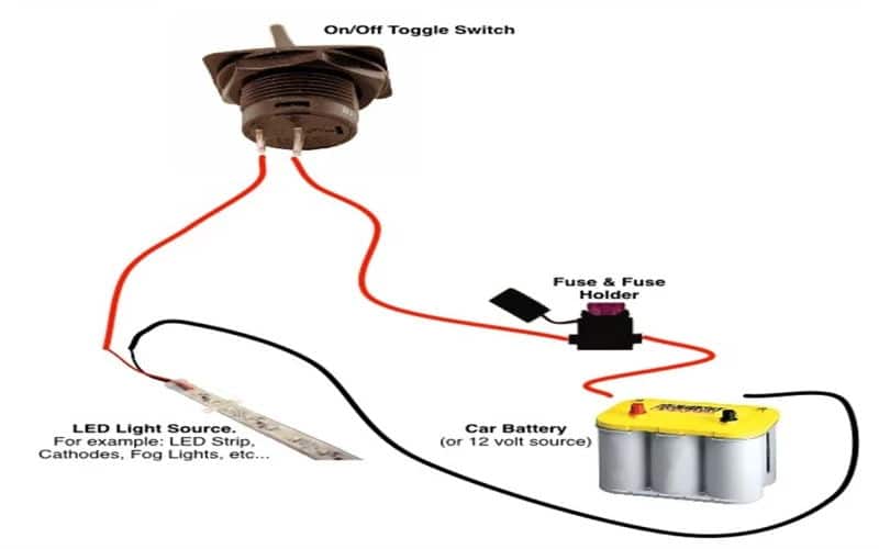
Credit: www.cweup.com
Prefer a documented repair or complete installation
If the vehicle already has a working original fuel-pump circuit, establish why a modification is needed. Convenience alone does not justify removing automatic control. If the original circuit is faulty, diagnose it before adding an alternate path. Delphi: loaded fuel pump voltage-drop testing explains why loaded supply and ground testing can reveal connection problems. A bypass that improves operation may point toward such a problem, but it does not locate the failed section by itself. If a technician is designing an aftermarket installation, ask for a schematic that identifies the pump, control device, protection, grounding and shutdown behavior. The drawing should match the actual parts and include any required manufacturer instructions. Ask how the system behaves during starting, normal running, engine stoppage and an electrical fault. A clear answer in each state is more useful than a promise that the switch is heavy duty. Do not use a temporary diagnostic lead as permanent wiring. Test equipment is installed for a controlled purpose and may not have suitable routing, sealing or protection for long-term vehicle use. Likewise, a loose relay or exposed connection under the hood is not completed merely because the engine runs. Permanent installation requires the approved mounting and environmental protection as well as correct electrical operation. After installation or repair, verify both normal operation and the intended shutdown functions using the documented method. Do not create a real crash or hazardous stall to test them. The installer should know the approved verification procedure for the chosen control system. Record the results and retain the schematic. Include the component part numbers and the date of installation so later repairs can preserve the intended design rather than substitute a visually similar but electrically different switch or relay. Future service becomes much harder when a hidden switch changes the circuit but no documentation explains it. Check fuel delivery as well as electrical operation. A switch that reliably powers the motor does not prove that the pump is correctly sized, regulated or supplied with fuel.
If the original complaint was low pressure or hesitation, those conditions need their own verification. Adding manual control can make a noise or starting symptom change without fixing the hydraulic problem. The repair should address the reason the work was undertaken. Tell anyone servicing or operating the vehicle about a retained custom control. Undocumented modifications can confuse diagnosis and create unexpected behavior during maintenance. Labeling and documentation should be appropriate to the installation, while preserving the necessary safety functions. If the vehicle is sold, the modification should not remain an unexplained secret in the wiring. A future owner needs to know how the system differs from the factory design. If the current setup is already a battery-to-toggle-to-pump bypass, have it assessed before normal use. Do not assume that adding another fuse or a larger switch resolves all concerns. The missing issue may be automatic shutdown, controller compatibility or a damaged original circuit. A qualified installer can determine whether the system should be restored or redesigned. The correct answer depends on the vehicle and intended use. A useful workshop request is to preserve normal fuel-pump safety control while resolving the stated problem. That directs attention to diagnosis and a complete design rather than to a particular switch someone saw online. Ask what component failed, why the proposed change is needed and how it will be verified. If those questions cannot be answered, the modification is not ready to install. The practical conclusion is that a toggle is only one component in a control system. Wiring it safely requires more than finding a positive terminal and a ground. Preserve the original controls where appropriate, use the exact approved schematic for custom equipment, and verify the system's behavior beyond the simple fact that the pump can be switched on.


Automotive reference information. Confirm specifications in the manual for your exact vehicle. Original replacement guides link to their research sources. About us