
An OBD2 scanner that will not work may have no power, may fail to communicate with the vehicle, or may lack the function you selected. Start by identifying which of those three problems is happening; they do not share one fix.
Record the scanner model, vehicle year and engine, exact message, ignition state and whether the tool ever worked on this vehicle. That short record prevents repeated guesses and gives support staff something specific to investigate.
Do not clear codes, bridge diagnostic pins or replace control modules to solve a connection problem. Begin with the manufacturer's connection instructions and the low-risk checks below.
Choose the correct troubleshooting branch
A dark display points first toward power and the tool itself. A powered display with a link error points toward connection or communication. A connected tool missing ABS, transmission or another function may simply have limited coverage.
Powered, but no vehicle link
Confirm the required ignition state and vehicle selection. An engine that is not running can still be available for many diagnostic functions, but the exact setup depends on the tool and application. Follow its connection sequence rather than repeatedly starting and stopping the engine.
No power at the tool
Innova: scanner power troubleshooting identifies vehicle supply and fuse problems as causes of an unpowered scanner. Use the vehicle's fuse information to identify the relevant circuit; do not assume every diagnostic connector shares the same accessory fuse.
Connected, but the desired menu is missing
A generic emissions reader is not automatically an all-module scanner. Check the manufacturer's function-level coverage for the vehicle. Buying an adapter or clearing codes cannot add software support that the tool does not provide.
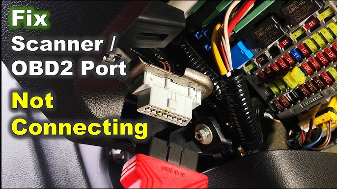
Credit: www.youtube.com
Inspect the physical connection
With the vehicle secured and the tool disconnected as instructed, inspect the accessible connector and cable for obvious damage. Do not insert metal objects or force a plug into place.
A plug that appears connected may not be fully seated. Check alignment and cable strain before trying again. Keep the cable away from pedals so the test setup does not interfere with vehicle control.Find the correct diagnostic connector
Use the vehicle's documentation to locate the diagnostic socket. An unfamiliar connector under the dashboard should not be treated as OBD2 simply because an adapter seems to fit.Look for damage without altering the terminals
Look for bent, recessed or visibly damaged terminals and a loose socket mounting. A damaged connector needs proper repair. Do not straighten powered terminals or push them with a screwdriver to improve contact.Avoid improvised cleaning
If contamination prevents connection, obtain an appropriate service procedure or have the connector cleaned professionally. Spraying an unknown product into an energized diagnostic socket can create a new problem.Verify vehicle and function coverage
A successful connection to one car does not establish compatibility with every vehicle. Market, model year, module and software coverage all matter.
Check the exact application
Confirm the tool's supported vehicle information and the specific task: generic codes, enhanced codes, live data or a service function. “OBD2 compatible” is not a promise of every manufacturer-specific feature.
Check software through the official channel
Use the tool manufacturer's update process and preserve existing reports first. Read any model-specific release guidance. An update can resolve a coverage issue, but it cannot repair missing vehicle power or a damaged connector.

Credit: www.youtube.com
Assess the supply before blaming communication
A weak vehicle battery or an interrupted diagnostic supply can make linking unreliable. A screen powered by the tool's own battery does not prove that the vehicle-side circuit is correct.
Battery and ignition state
Note whether the vehicle has other electrical symptoms, such as dim displays or difficulty cranking. Use the vehicle's prescribed battery assessment where needed. Do not diagnose the communication network solely from a low-voltage event.
Cable condition and substitutions
Check detachable connections and use only suitable replacement cables or adapters. An arbitrary cable that fits mechanically may have different wiring. If substituting a known-good tool or cable, document exactly what changed and what result followed.
Wireless adapters add another connection layer
A phone can communicate with an adapter while the adapter has no vehicle link. Treat phone-to-adapter pairing and adapter-to-vehicle communication as separate checks.
Pair using the adapter's instructions
Confirm the supported app, connection type and required device permissions. Some adapters connect within the app rather than through the phone's general pairing menu. Use the manufacturer's method for that exact model.
Watch the actual connection state
An icon showing Bluetooth or Wi-Fi availability does not prove that diagnostic data is arriving. Check the app's vehicle-link status and any error message. Save the wording instead of reducing every failure to “bad signal.”
App and operating-system checks
If the adapter is recognized but the app cannot link, confirm the selected adapter and vehicle profile. Close other diagnostic apps that might be attempting to use the same adapter, then follow the prescribed reconnection steps.
Update without losing the diagnostic record
Save logs before reinstalling or resetting the app. Reinstallation can remove settings and previous reports, so it should be a targeted support step rather than the first response to every failure.
Use official software sources and check the supported operating-system version. Avoid unofficial firmware intended for a different adapter; a similar housing is not evidence of identical electronics.
Permissions and device support
Review only the permissions needed for the documented connection method. If the phone or operating system is unsupported, test with a supported configuration rather than assuming a vehicle fault.
Note whether the issue began after an app or phone update. That timing is useful to the vendor, especially if the same adapter still works with another supported device.
Keep the vehicle conditions consistent while comparing setups. Otherwise an ignition-state change can be mistaken for an app fix.
Once the connection is stable, return to reading information before trying advanced commands. A successful link is not authorization to perform every service function displayed.
Use the right documentation for each question
The vehicle manual helps locate the connector and relevant fuses. Scanner documentation, such as the Innova 3160b scanner manual, explains tool operation. Service information may be needed for electrical or network diagnosis beyond those owner checks.
Keep those sources separate: a scanner's example vehicle does not define the fuse layout or network architecture of your car.
Manufacturer-specific access
Some functions require enhanced coverage or additional authorized access. Follow the vendor's supported process. Do not attempt to bypass a security gateway or alter wiring because a generic tool cannot perform a protected function.
A missing service function is not the same as a complete communication failure. Tell the tool supplier which module and operation are unavailable so they can answer the actual coverage question.
When basic checks have not resolved it
If the tool powers up and the supported setup is correct but no link can be established, professional diagnosis may be needed. The next checks should be based on the circuit and network information, not random pin probing.
Stop if a fuse repeatedly fails, the connector is damaged or there are broader electrical faults. Replacing fuses with a higher rating or bridging a circuit is not a safe workaround.
Bring the troubleshooting record to the appointment. It can prevent the workshop from repeating steps that were already performed correctly.
What to ask a diagnostic specialist
Ask whether the problem is supply, connector integrity, network communication, a specific module or tool coverage. Those findings lead to very different repairs.
A control-module replacement should have supporting electrical and communication tests. The absence of a scanner link by itself does not establish that the module has failed.Evidence before replacing a module
Seek help when a supported known-good setup still cannot communicate or when there is visible damage or an electrical symptom. Provide the exact error, vehicle details and what was already checked.Verify the original complaint after repair
Choose a workshop with the appropriate coverage and service information for the vehicle. Ask for a written diagnosis that identifies the failed path and the final communication check, rather than just a replacement recommendation.
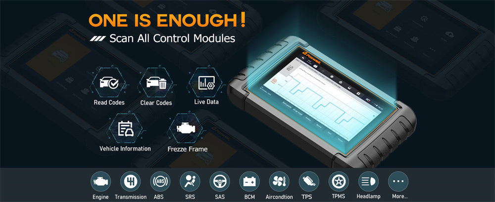
Credit: www.foxwelldiag.com
After the scanner connects
Confirm that it reads the expected vehicle and data. Our live-data guide explains interpretation; the separate INC readiness guide explains monitor status.
Keep power, communication and function coverage distinct. A fix for one layer does not prove every other layer is working, but it does give you a clear next check.
The goal is a stable, supported connection with an understood error history—not a series of resets that happens to produce a working screen once.


Automotive reference information. Confirm specifications in the manual for your exact vehicle. Original replacement guides link to their research sources. About us