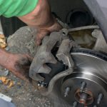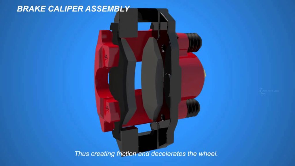

A car’s disc brake slows a rotating wheel by pressing friction pads against a rotor. The caliper positions and applies those pads using hydraulic pistons in a conventional hydraulic system. Pressure provides the applying force, friction resists rotation and the braking components absorb and dissipate heat. When the driver releases the brake, pressure and mechanical movement must return to the intended released condition.
Understanding that whole cycle is more useful than thinking of a caliper as a clamp that simply opens and closes. This article follows the system from input to release and explains how the major parts depend on one another. It covers automotive disc-brake calipers, not bicycle rim-brake mechanisms that also use the word caliper.
Designs vary, including fixed and floating arrangements, integrated parking brakes and electronically controlled systems. The operating principles help explain symptoms, but they do not identify a failed part from a noise or hot wheel alone. Repair instructions must still match the actual vehicle.
From a driver’s request to force at the wheel
In a conventional arrangement, pedal input acts through the brake-assistance and master-cylinder system to generate hydraulic pressure. The fluid circuit carries that pressure to the wheel brakes. Details differ where electronic control or alternative assistance systems intervene, so the pedal should not be imagined as a direct mechanical cable to every caliper. The wheel brake receives hydraulic force through its assigned circuit and converts it into pad loading.
The amount of force depends on the system’s design as well as the pressure supplied. The rotor turns with the wheel assembly while the pads are supported against rotating with it. Contact between their friction faces resists rotation. The resulting loads pass through the caliper’s supporting arrangement and the vehicle structure.
That is why a secure mounting and correct bracket geometry matter even when the hydraulic seals are sound. A caliper is not just a container for fluid; it is also part of the load path during braking. Braking transfers energy into heat, so a warmer brake after use is not inherently a fault. The important distinction is between expected operation and abnormal temperature or continued application.
A brake that remains applied can keep producing heat after the driver expects release. One unusually hot corner therefore calls for investigation rather than an automatic conclusion that a piston has failed. Pressure retention, pad fit and parking-brake issues can produce overlapping results. The system also needs enough tire-to-road grip to transmit braking force.
A more powerful-looking caliper cannot eliminate that limit or guarantee a shorter stopping distance. Vehicle stability and electronic control strategies further affect how available braking is used. Avoid judging overall performance by the number of pistons visible through a wheel. The components work as a specified system rather than as isolated parts ranked by appearance.

Credit: haynes.com
The components form one operating chain
The hydraulic supply, pistons, seals, pads, rotor and supports each perform a different role. A fluid leak interrupts pressure containment. Binding support hardware can impede movement despite normal pressure. Worn or contaminated friction material can affect braking even if the caliper moves correctly.
This distinction explains why diagnosis should follow the observed behavior instead of assigning every brake complaint to the caliper housing. Think of a braking event as three linked questions: did the required force reach the wheel, did the friction assembly respond correctly and did it release afterward? A good inspection considers all three. A firm pedal answers only part of the first question, and a freely rotating wheel after cooling does not answer every question about release under the original conditions.
Pads provide the intended friction interface
Brake pads place purpose-designed friction material against the rotor. Their backing and supporting hardware locate them within the assembly, and their exact fit matters. They must operate without unintended binding or movement. A pad that appears to fit loosely in one direction may still be wrong for the application or incorrectly supported. Correct identification and installation are therefore part of brake operation, not merely a purchasing detail.
The friction faces should not be lubricated. Grease applied to stop squealing can contaminate the very surface needed to resist rotation. Some backing or support contacts may have specific maintenance instructions, but those do not authorize coating the friction material. Wear patterns can provide diagnostic clues, although no single pattern uniquely identifies every cause. Our brake-pad thickness guide explains why inspection needs to distinguish pad material from the backing and consider the relevant service limits.
Fixed and floating calipers achieve clamping differently
A fixed caliper remains mounted in position and uses opposed piston arrangements to apply pads from the two sides. A floating caliper uses movement of its body relative to its support so that the applying action also loads the opposite pad. Brembo’s fixed-versus-floating explanation describes this basic distinction. Both are disc-brake designs, and neither term by itself declares a particular vehicle’s brakes good or bad. The correct configuration depends on the application. On a floating design, the guide arrangement must move as intended for the assembly to work normally.
Restricted guides can upset pad loading and release. HELLA’s guide-pin guidance connects such restriction with wear and overheating concerns. A piston that retracts successfully does not prove those guides are healthy. On a fixed design, a different arrangement of pistons and passages requires its own service checks. Applying a floating-caliper maintenance procedure to a superficially similar fixed body can therefore be inappropriate.
Pistons and seals contain pressure and permit movement
Hydraulic pressure acts on the piston arrangement to move the pads into their working relationship with the rotor. The hydraulic sealing components must contain that pressure while accommodating the designed piston movement. Dust protection, where fitted, serves a different role by limiting environmental contamination. A torn protective boot and a leaking pressure seal are related inspection concerns, but they are not the same component or an identical diagnosis. The brake does not normally create a large visible air gap after every pedal release.
Its small operating clearances and seal behavior are design-dependent. As friction material wears, the piston’s working position changes accordingly; it does not return to the exact new-pad position at every stop. Pad replacement can consequently require a specified piston-retraction procedure. That service movement must respect any integrated parking mechanism. See the piston-retraction explanation before assuming every piston should be forced straight inward with a clamp.
Fluid pressure connects the components; air changes the response
Brake fluid carries hydraulic pressure through the system and must meet the vehicle’s required specification. It is not a lubricant to choose by an arbitrary higher grade number. The manufacturer’s fluid and maintenance requirements account for the intended materials and operating conditions. Opening a connection also creates a need to control contamination and restore the hydraulic system correctly. A circuit that lost only a small amount of fluid may still contain air afterward.
Air is much more compressible than the liquid, so an air pocket can consume movement and change pedal response. A soft or long pedal is therefore a concern requiring assessment, but it does not establish which component failed or whether air is the only issue. Pressure that remains after release is a different problem from compressibility. A brake can drag while the pedal feels firm, or it can have more than one fault at once. Electronic control can alter pressure at individual wheels as conditions require.
HELLA’s ABS and ESP overview describes a hydraulic unit containing valves used to control wheel-brake pressure. That helps explain why service procedures may involve more than a simple tube from the master cylinder to a caliper. It does not mean every caliper change requires the same scan-tool routine. The actual system and repair condition determine the necessary method.
Application, release and parking are separate checks
During an ordinary braking event, the driver requests slowing, the system develops and controls pressure, and the calipers apply the pads against the rotors. When that request is removed, the relevant pressure and moving parts must return to their intended condition. The important test is correct application and release, not whether a component looks new. A visually clean caliper can contain a defect, while light exterior discoloration need not establish a functional failure.
Parking-brake operation adds another distinction. Some rear calipers contain a mechanical or electric parking mechanism, while other vehicles use a separate arrangement. HELLA’s integrated-handbrake guidance shows why an integrated design has service considerations beyond the main hydraulic action.
A dashboard switch in the released position is not proof that every wheel mechanism returned correctly. Conversely, not every rear disc brake has the same internal parking mechanism. Identify the system rather than inferring it from wheel position alone.
If a brake fails to release, the technician investigates mechanical resistance and retained hydraulic force as separate possibilities. Guides, pad supports, pistons and parking components need appropriate checks. The supply path may also require assessment.
Our brake-hose restriction guide explains why an apparently stuck caliper can have an upstream cause. Replacing friction material alone does not resolve every problem in this operating chain. If braking is impaired, fluid leaks, a wheel smokes or the vehicle pulls severely, stop safely and arrange assessment rather than testing the explanation on the road.
The principles are useful for describing symptoms and understanding a repair estimate, not for bypassing a safety fault. A complete service verifies mounting, routing, sealing, pedal response and the relevant application-and-release functions before normal use. The caliper’s job makes sense only in that wider system: it must receive the right force, transmit it through correctly fitted friction parts and release reliably when the operating condition requires it.


Automotive reference information. Confirm specifications in the manual for your exact vehicle. Original replacement guides link to their research sources. About us