
Putting a ball joint into a steering knuckle can describe two different operations. This guide covers connecting the joint’s stud to the knuckle, especially a tapered-stud connection. It does not provide a universal method for pressing a joint housing into a suspension component.
Identify the connection before selecting tools or applying force. Some vehicles instead use a clamped stud and pinch bolt, which requires its own procedure. The objective is a correctly matched, securely retained connection with an undamaged protective boot and unrestricted intended movement.
- A nut that can be tightened is not, by itself, proof that the stud fits the knuckle. Use the vehicle repair instructions and any applicable instructions supplied with the exact replacement part. If the connection cannot be assembled as specified, resolve that problem before the vehicle returns to use.
Identify the connection and inspect its receiving surface
-
Start with the vehicle identity and the position of the joint being connected. Upper and lower connections can differ on the same vehicle.
- A part chosen by an approximate visual match is not sufficient. Confirm the application, suspension option and replacement part number.
- A previous modification may mean the vehicle no longer has its original suspension arrangement. Record any aftermarket control arm or knuckle before ordering.
-
Locate the stud connection in the service information. A tapered stud enters a matching tapered receiving hole.
- Its fastening method differs from a straight stud retained by a pinch bolt. The housing attachment elsewhere on the joint is a separate interface.
-
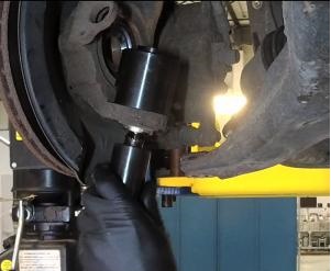
A press kit intended for that housing does not determine how the stud should be seated. Keeping those operations separate prevents force being applied to the wrong surface.
- Check the old connection before cleaning removes useful evidence. Note looseness, unusual polished areas and damaged hardware.
- Photograph visible problems if their origin matters to the repair decision. Damage introduced while separating the old part should be identified separately.
-
A newly scratched surface is not proof of long-standing movement. If removal damaged the receiving component, include that damage in the replacement decision.
- MOOG’s stud-fit bulletin directs installers to check the receiving taper and warns that a loose or damaged fit can require knuckle replacement. Its warning is about the structural connection, not merely the condition of the nut.
- A new joint cannot repair a worn receiving hole.
- Tightening harder does not restore the original geometry.
- Stop if the stud rocks or the connection does not seat as the applicable instructions require.
- Inspect the surrounding component as well as the hole.
-
Look for cracks, distortion and damage around the mounting area.
- A damaged knuckle needs a repair decision before assembly continues.
- Do not reshape the taper with a drill or improvised abrasive tool.
- Such alteration changes the surface on which the connection depends.
-
Consult the approved replacement or repair route instead.
- Prepare the receiving surface using the specified method.
- Remove unwanted contamination without altering its shape.
- Do not assume oil, grease or anti-seize belongs on the taper.
- Lubrication instructions must come from the applicable assembly procedure.
The same caution applies to the stud threads.
A torque specification cannot be separated from the conditions under which it is intended to be used.
Check that the new stud and supplied hardware belong together.
Compare identification information rather than relying only on a similar nut size.
Threads that begin to engage do not establish correct fitment.
Credit: www.delphiautoparts.com
Damage, mismatched pitch or an incorrect fastener can prevent reliable retention.
Set aside questionable parts until their specification is resolved.
- A clean work area makes small retainers and differences in hardware easier to track.
Align and seat the stud using the specified arrangement
-
Support the vehicle and suspension at the locations required for this operation. A hanging assembly may not be positioned as the installation procedure expects.
- The support plan must account for suspension loads. Do not work beneath a vehicle supported only by a lifting jack.
- Keep hands clear of areas where the arm or knuckle could move suddenly. If the necessary support arrangement is unknown, obtain the procedure before continuing.
-
Position the assembly so the stud approaches its receiving hole without side loading. Check what limits the knuckle’s movement.
- A brake hose, wheel-speed-sensor lead or driveshaft must not become the support strap for the assembly. Restore the intended support rather than pulling against those components.
-
Move only within the limits of the vehicle’s service procedure. A connection that will not align may indicate a positioning or fitment problem.
- Protect the dust boot during this stage. Keep its edge clear of any surface that could pinch it.
- Check the part instructions for the boot and retaining arrangement. MOOG’s dust-boot installation guidance illustrates why boot installation is a defined part of the job.
-
A boot that looks attached may still be incorrectly seated. Recheck it after the joint reaches its installed position.
- Introduce the stud as the specified connection requires. Avoid using the retaining nut to disguise an obviously misaligned start.
- Start the correct nut by hand where the instructions call for that approach. It should engage evenly rather than cut its way through damaged threads.
- Unexpected resistance deserves investigation. Removing and checking the nut early is preferable to damaging both pieces.
- A stud may rotate while a nut is being installed. That observation does not automatically mean the joint is defective.
- The correct response depends on the connection and the provisions built into the part. Some designs provide a defined counterholding feature.
-
Others require a specific seating arrangement described by the manufacturer.
- Do not generalize a method from another vehicle merely because its stud also turns.
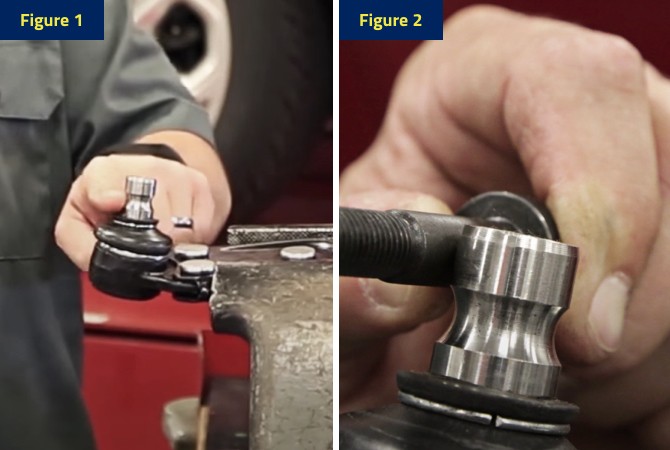
- Avoid gripping the polished or working surface of a stud with locking pliers.
- Do not puncture the boot to gain access.
-
An impact wrench is not a substitute for resolving why the connection will not seat.
- Nor is lifting an arbitrary suspension point a universal seating method.
- The required load path and support conditions must be known.
- Stop when those conditions cannot be established safely.
- For a pinch-bolt design, follow its separate insertion and retention instructions.
A groove or positional feature may need to align with the retainer.
Never apply a tapered-stud procedure simply because both assemblies connect a joint to a knuckle.
Verify the specified bolt, orientation and replacement requirement.
A bolt passing through an opening is not proof that the joint is at the correct depth.
Use the manufacturer’s stated acceptance checks.
Before final tightening, inspect the whole connection again.
Confirm there is no trapped wire or displaced protective component.
Confirm that the hardware sits against the intended surface.
Credit: www.delphiautoparts.com
Check that the part is not being forced to compensate for a wrong application.
Resolve any unexplained gap by reference to the correct illustration or instructions.
- Do not assume every visible gap is either normal or defective without that context.
Verify fastening, retention and the completed assembly
-
Use the tightening specification for the exact connection and replacement part. There is no useful universal ball-joint nut torque.
- An upper joint, lower joint and pinch-bolt connection may have different requirements. Some procedures specify additional steps beyond a single torque value.
- Read the complete sequence before beginning. Prepare a suitable calibrated tool and the necessary access.
-
Follow the stated hardware replacement rules. A removed self-locking nut should not be treated as interchangeable with a new supplied nut.
- MOOG’s fastener bulletin explains a specific case in which the supplied flange geometry matters to the connection. Its example demonstrates why a similar-looking substitute is not enough.
-
Keep the part’s instructions with the hardware until assembly is complete. Do not add washers or swap nut styles to make an unexplained fit problem disappear.
- Use the specified final tightening method. A power tool’s setting does not establish the achieved assembly torque.
- Extensions or adapters may require consideration under the tool instructions. If access prevents a reliable final measurement, solve the access problem.
-
Do not declare the job complete because the fastener feels tight. Record the specification source when documenting the repair.
- If the design uses a castle nut and cotter pin, apply its stated alignment procedure. Do not casually back off a tightened nut to make a hole visible.
- The applicable instructions determine how alignment is achieved. Install the correct locking component and verify its placement.
- A missing retainer remains a defect even when the nut was initially tightened correctly. Check self-locking and pinch-bolt arrangements according to their own requirements instead.
- Inspect the boot around its full accessible perimeter. Check for a trapped lip, tear or unwanted contact.
- Confirm that any supplied retaining component is correctly fitted.
-
Follow product-specific lubrication instructions for a serviceable joint.
- Do not inject grease into a sealed design.
- Wipe away excess material only as appropriate to the part and surrounding components.
- Recheck everything disturbed to reach the joint.
-
That can include brake-hose supports, sensor-wire routing and wheel fasteners.
- Confirm that the suspension and steering can move as the procedure requires without stretching a line.
- Determine whether wheel alignment is required after this particular repair.
- Complete the specified safety checks before any road verification.
- An unresolved fastening or fitment problem is a reason to keep the vehicle out of use.
For the earlier diagnostic question, see how ball-joint squeaks are distinguished from nearby noises.
For the durability question, see why ball joints deteriorate.
Neither diagnosis nor a new part number replaces installation verification.
The completed connection must satisfy its own fit, fastening and protection requirements.
If any of those remain uncertain, have a qualified repairer inspect the assembly before it is driven.


Automotive reference information. Confirm specifications in the manual for your exact vehicle. Original replacement guides link to their research sources. About us