A brake-line double flare is a formed tube end that must match the receiving seat, tube nut and brake-line specification. Making one successfully involves more than pressing metal into a cone. Identify the required connection first, use a suitable tool and inspect the result before the line enters service.
A leak should never be treated as a reason to tighten an unsuitable flare harder. This guide explains the decisions and checks around a conventional inverted double flare. It is not a universal operating procedure for every flaring tool or brake system.
The exact tool instructions govern the forming stages, tube projection and permitted materials. The vehicle procedure governs the hydraulic repair, tightening, bleeding and final verification.
Credit: blog.1aauto.com
Confirm that this connection actually requires a double flare
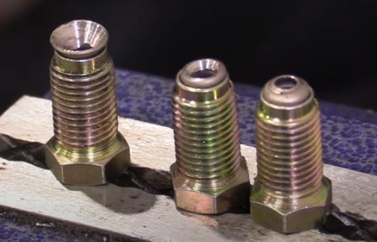
Do not select a flare solely from the vehicle’s country of manufacture or the thread appearing metric. AGS’s flare-identification guide distinguishes inverted double and ISO bubble connections and explains that thread type alone does not identify the flare. Check the service information, receiving seat and correct replacement specification. A damaged old end may be useful evidence, but it is not a reliable template if its shape has already been distorted.
The tube diameter, nut threads and seat geometry must work together. A nut that screws into a port does not prove that the tube end seals against it correctly. Identify both ends of the line because they need not have identical hardware. If an adapter is required, it must be specified for the intended brake connection; assembling available fittings until the threads engage is not a compatibility check.
Choose tubing, nuts and tooling as a matched system
- Use tubing specifically suitable for the vehicle’s brake system and permitted repair. Do not substitute ordinary plumbing tube or unidentified material. Check the flaring tool’s permitted materials, sizes and flare forms. A tool that can form one kind of soft tube may not be approved for another material with different forming requirements. The die must match the actual tube size rather than the nearest hole in a kit. Have the correct tube nuts available before forming either end. Check thread diameter, pitch, length and the intended flare seat. Inspect the tool for damaged dies, contamination and worn clamping surfaces. A faulty tool can create a defective end even when the operator follows the sequence. If you cannot verify the necessary equipment and specifications, a correctly matched pre-flared line or professional fabrication may be the better repair route.
Prepare a clean, square tube end
- Plan the line length and route before cutting. Include the allowance required by the tool and fitting arrangement without guessing at a universal number. Preserve a usable original line as a routing pattern when appropriate, while checking that its route was correct. Our guide to preparing straight brake tubing discusses starting from new coil without trying to rescue a kinked service line. Make the cut with equipment suitable for the tubing.
- Prepare the end as the tubing and tool manufacturers specify, removing burrs without leaving contamination inside. A visibly uneven end or damaged tube wall needs correction before forming. Do not compensate for poor preparation with additional forming force. Keep the inside clean throughout the job and use the manufacturer’s cleaning method rather than introducing an arbitrary solvent.
- Slide the correct nut onto the tube in the correct direction before forming the end. Check that it can move where it needs to during installation. This small sequencing detail matters because a completed flare usually prevents the nut from being added afterward. If the nut is wrong or omitted, plan a proper remake with sufficient remaining line length instead of modifying the nut or flare.
Set the projection and clamp for the actual tool
- Read the tool’s setup instructions before clamping. Tube projection is a tool-specific setting, not a dimension that should be borrowed from a different brand’s tutorial. Some tools use a die feature or gauge to establish position. Others use a different locating arrangement. Confirm the setting for the selected flare and tube size before applying the forming operation.
- Hold the tube squarely in clean, correct-size jaws. The clamping arrangement must prevent unwanted movement without damaging the tube. Check that the forming element will approach in alignment. A tube that shifts, tilts or shows unexpected clamping damage is a reason to stop and reset. Repeatedly tightening a slipping setup without finding its cause can spoil both the workpiece and the tool.
Understand the forming stages without substituting a recipe
- A conventional inverted double flare uses a folded tube-end structure. Many familiar tools produce that structure in successive forming operations, but the actual die sequence and operating stops come from the tool manufacturer. Do not assume that the first stage of one tool is an acceptable bubble flare for another connection. The required finished form is defined by the connection, not by an intermediate shape that happens to resemble it. Apply only the lubrication, force method and stroke specified for the tool.
- A longer handle, impact wrench or improvised press is not an automatic improvement. If the tool does not operate as expected, release and inspect it according to its instructions. Confirm that the tube has not slipped and that the correct forming element is installed. Unusual resistance should trigger a setup check rather than an experiment with greater force.
- Keep the work supported so the line’s weight does not pull the end out of alignment. For long sections, provide room to manage the remaining tubing safely. Protect the open end from dirt while changing tools or repositioning the work. A good-looking flare is only one part of a clean and correctly routed hydraulic line.
Recheck the setup between tool operations
- Where the tool requires a change of forming element, follow the stated order and preserve the established tube position. Check for movement before continuing. Do not adjust projection midway merely to make an imperfect first shape look better. If an error has occurred, the correct response may be to cut off the end and prepare a new section.
- Consider the remaining usable length before remaking an end. Several retries can leave the line too short for its intended route. Pulling the shortened line tight between ports creates a different installation defect. Replace the section if necessary rather than sacrificing support, clearance or connection alignment to save material.
Inspect the completed flare before installation
- Look for an even, centered form appropriate to the specified connection. Reject visible cracks, splits, damaged sealing surfaces or a markedly uneven shape. Check the tube immediately behind the flare for distortion and tool damage. A defective end should be remade using sound material and the correct setup; sealant does not repair its geometry. Compare the result with the tool manufacturer’s acceptance examples and the required fitting design. Do not use a trial tightening operation to reshape an obviously defective flare. If the quality remains uncertain, have someone competent in brake-line fabrication assess it before installation.
Verify the entire hydraulic repair, not just the new end
- Install the line according to the vehicle procedure with the correct routing and support. Avoid using the tube nut to pull a misaligned line into position. Start connections correctly and use the specified tightening method and value.
- Threads provide the clamping action for the flared connection; adding an unapproved sealing compound is not a remedy for a damaged or mismatched seat. AGS’s NiCopp assembly instructions emphasize matching the flare, following the flaring tool’s directions and retaining the intended supports. Those fabrication points do not replace a vehicle-specific bleeding procedure.
- Some systems require particular equipment or electronic service steps. Establish that requirement before opening the hydraulic circuit, not after the replacement line is installed. Complete the required fluid, bleeding and leak checks before the vehicle is moved.
- Use only the specified fluid from an appropriate clean supply. A firm-feeling pedal alone does not certify every new connection. Inspect the repaired area under the prescribed test conditions and resolve any seepage, abnormal pedal behavior or warning indication.
Do not drive to find out whether a questionable repair will hold. HELLA’s brake-line guidance identifies corrosion and external damage as inspection concerns and emphasizes manufacturer instructions. Check adjacent sections as well as the repaired end.
If the original failure reflects widespread deterioration, a small local repair may leave other unacceptable sections in service. The repair scope should follow the actual condition and the permitted repair method.

Credit: www.amazon.com
Questions to resolve before accepting a double-flare repair
Can one tool make every brake-line connection? No; check its specified flare forms, tube sizes and materials.
A broad kit description does not establish suitability for your particular line. Can the original nut be reused?
Only if the applicable repair instructions permit it and its condition and specification remain suitable. Rounded flats, damaged threads or uncertainty about the original part are reasons to reassess it.
Does a flare that does not leak immediately count as correct? Not by itself.
Fitment, material, preparation, routing and the specified verification all matter. Can a single flare replace the required inverted double flare?
Do not substitute a different construction for the specified brake connection. Can a bubble flare be tightened into an inverted-flare seat?
The connection types must match rather than being forced together. What should an owner ask the workshop?
Ask which line is being replaced, why that scope was selected, how the connection type was confirmed and what final tests are included. If a stubborn old connection complicates removal, see the decisions around seized brake-line fittings.
The correct outcome is a sound, supported hydraulic repair, not merely a newly shaped tube end.


Automotive reference information. Confirm specifications in the manual for your exact vehicle. Original replacement guides link to their research sources. About us