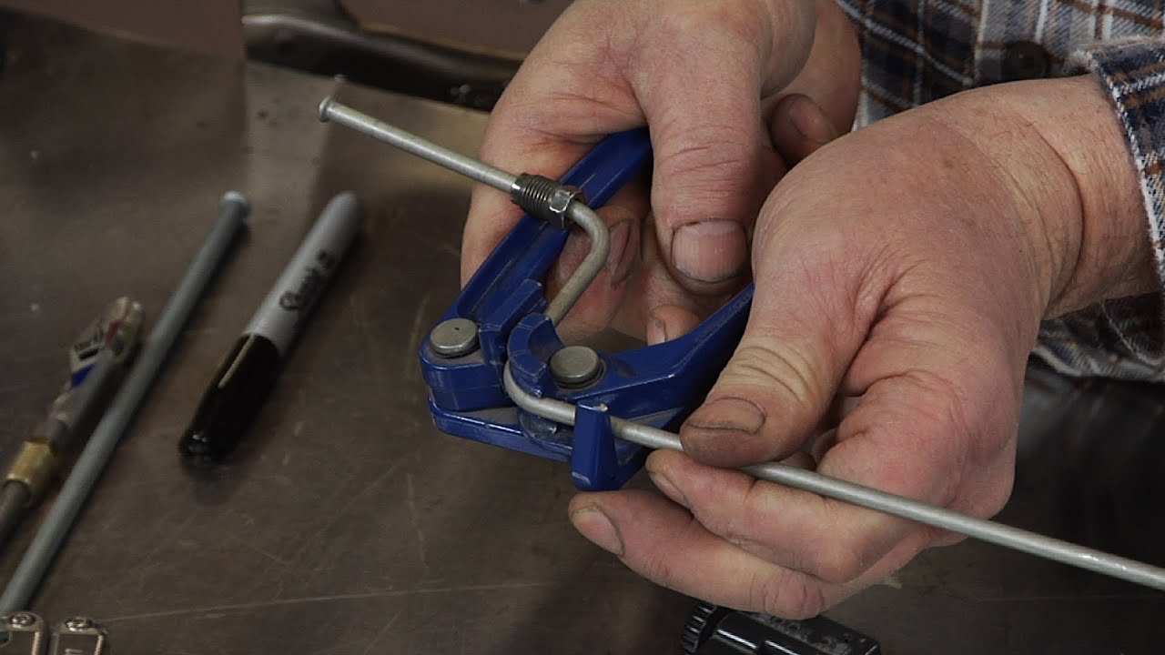

Bend a replacement brake line with equipment suitable for its material and outside diameter, following the tube supplier's limits and the vehicle's required route. The objective is a correctly formed line that reaches its connections without strain and remains supported and clear of surrounding components.
There is no universal minimum bend radius for every brake tube. A tool's groove, radius and capacity must suit the selected tubing, and the completed shape must fit the application.
Do not heat a line, crush it with pliers or straighten a kink as an improvised repair.
This is a planning and inspection guide; opening and restoring the braking system also requires the full vehicle service procedure.
Credit: www.roadandtrack.com
Start with the route and the replacement specification
Identify the line being replaced and why replacement is required. Record its connections, supports and clearances while the original route can still be understood safely. Do not reproduce accidental damage or a poor earlier repair just because it is already on the vehicle. Confirm the correct material and dimensions before selecting a bender. A preformed application-specific assembly may avoid fabrication steps, but it still needs correct identification and installation. If a route is partly hidden, obtain the service information rather than guessing where a replacement can safely pass.
The line should fit the vehicle without using its fittings to pull it into position. A shape that reaches both ports only when forced needs reassessment. The intended supports should locate it without creating a strained bend. Allow access for the correct fastening and inspection tools at each end. Check whether a flare must be formed before or after particular bends under the chosen procedure. Planning those details before cutting reduces the chance of discovering that a finished nut or flare cannot pass the next obstruction.
Choose equipment for the actual tube
RIDGID’s 400-series specifications list different capacities and bend radii by tool model. This is evidence that a tubing bender has defined geometry, not permission to apply one radius to every brake line.
- Confirm material, wall specification and diameter compatibility for the selected tool. A groove that nearly fits is not an adequate match.
- The vehicle route and tube requirements must also permit the resulting bend. Prepare the correct measuring, cutting and tube-preparation tools along with the bender.
- Obtain any required flaring equipment and matching fittings. Keep the tubing clean and protected from contamination.
- Inspect the bender's forming surfaces and moving parts before use. A damaged or dirty groove can affect the result.
- Have the instructions available at the work area rather than relying on remembered markings from a different model. A complete tool plan includes inspection of the formed line, not merely the ability to move the handle.
Plan the sequence before forming the first bend
Sketch the route with reference points that can be checked against the vehicle. Identify the ends, the plane of each bend and the location of supports.
- Mark the tubing using a method that does not damage it. Leave the length and end allowances required by the complete fabrication procedure.
- Do not assume that a straight-line measurement between ports is the correct finished tube length. Curves and fitting preparation affect the material needed.
- Read how the selected bender's marks relate to the bend being formed. RIDGID’s 600-series instructions explain tool-specific positioning and measurement considerations.
- Use that document only for its covered tool, and use the equivalent instructions for another model. An alignment mark can refer to a particular edge or direction, so copying a video without matching the tool can put a bend in the wrong place.
- Confirm the setup before applying forming force. Work through the planned sequence while maintaining the correct orientation.
- A bend in the wrong plane may prevent the line from following its supports even when its angle looks correct from one side. Compare the developing shape with the route at safe opportunities.
- Do not force the line against the vehicle to hide an alignment error. If a bend would block the tool from making the next required bend, revise the fabrication sequence before proceeding.
- The amount of forming movement and any springback allowance depend on material and tool instructions. Do not use a universal extra angle for all tubing.
A test piece of the same specified material can help a competent fabricator understand the setup, but it does not replace the manufacturer's limits.
Keep trial work separate from the installed hydraulic line.
Reject an uncertain part rather than relying on the fact that it can still be made to reach the port.
Recognize unacceptable deformation
Inspect each formed area for a kink, crease, crack or other damage that would make it unsuitable. A visibly flattened or sharply folded section should not be squeezed back into shape and returned to service. The supplier's acceptance requirements govern any allowable dimensional change.
Appearance alone cannot establish every property, but obvious damage is a reason to stop. Do not hide a compromised section beneath a protective sleeve or support clip. Excessively tight bends can also create a route that is difficult to secure or inspect.
A bend that just clears a stationary component may not satisfy the required movement clearance. Check the complete installed environment rather than judging the curve on the bench alone.
If the route cannot be achieved within the specified forming limits, obtain the correct preformed line or a supported alternative. Do not change the limits to suit a convenient tool.
Check routing, support and connection access together
Use the intended mounting points and the specified clips or retainers. A loose run can move into contact with surrounding parts, while an incorrectly positioned support can strain the line.
- HELLA’s line guidance highlights installation and damage concerns, including correct routing. The practical lesson is that a good-looking bend is only one part of a sound line installation.
- The completed route must be assessed as an assembly. Check clearance from moving suspension or steering parts under the prescribed procedure.
- Consider the specified protection around heat and abrasion sources. Do not substitute a route next to an exhaust component because it is shorter.
- Do not allow the tube to become a support for wiring or another hose. If access requires vehicle lifting, use proper support and the application-specific service method.
- Never crawl beneath a vehicle held only by its jack. At the connections, confirm the correct nut and flare before final assembly.
- A bent line with the wrong end cannot be corrected by forcing its threads into a port. Our diameter, thread and flare guide explains that identification task.
- The nut must be present at the appropriate fabrication stage and remain usable after forming. Access for tightening must not depend on bending the installed line out of the way repeatedly.
- Keep open ends protected as required by the repair instructions. Tube cutting and preparation can produce debris, and cleanliness belongs to the entire process.
- Do not flush an assembled brake system with an improvised solvent to compensate for careless fabrication. Use the specified materials and procedures from the outset.
- If contamination is suspected, assess it before the vehicle returns to service. Once installed, complete the prescribed hydraulic restoration and checks.
This can include bleeding and vehicle-specific operations depending on what was opened. A line that fits mechanically still needs leakage and functional verification.
Do not infer successful braking from the shape alone. If a connection leaks, investigate the actual sealing problem rather than altering an adjacent bend to load the fitting differently.
Can a brake line be bent without a dedicated bender?
Some tubing products may permit particular hand-forming methods, but that permission must come from the product guidance and suit the required shape. It is not a universal instruction to form every brake line by hand. Material, dimensions and bend radius matter.
A line that feels easy to bend is not automatically suitable for the braking system. Confirm the product first, then the supported forming method.
Avoid treating hand strength as process control
- An unsupported hand bend can concentrate force at one point or produce an uneven curve. Pliers and improvised handles can damage the surface or flatten the tube. Do not assume that careful handling makes those methods equivalent to a specified tool.
- If the required forming operation is beyond the equipment available, change the work arrangement. A correctly identified preformed replacement or professional fabrication may be the practical answer. Do not repeatedly reverse a bend to chase the final position.
- If the line has been damaged or its acceptability is uncertain, replace the affected fabrication with a properly prepared piece. Material behavior and permitted reworking depend on the product, so there is no universal number of safe corrections. The objective is a sound finished line, not salvaging every length already cut.
Why improvised bending fixtures need caution
- A homemade form can resemble a tubing bender without providing controlled support or the correct radius. Its surface, groove and retention may not match the tube.
- That is not a reliable basis for a safety-critical hydraulic line. Use documented equipment and methods rather than a household object selected because its diameter looks close.
- Do not heat the tube to make an unsuitable form work. Do not pack it with an improvised material that may contaminate the line.
Do not hammer a crease flat. These shortcuts change the problem instead of demonstrating an acceptable bend.

Credit: m.youtube.com
Before approving the completed work, review the line from end to end. Confirm its specification, route, supports, connection fit and visible condition.
Verify that the repair record includes the hydraulic restoration and checks. Ask for clarification if the installer cannot explain a departure from the original supported route.
Keep any follow-up instructions with the invoice. The finished result should be a properly supported line that meets the application requirements, not merely a replacement that looks similar from a distance.
If the original issue was leakage, our leak-repair guide places this fabrication step within the broader diagnosis and verification process.


Automotive reference information. Confirm specifications in the manual for your exact vehicle. Original replacement guides link to their research sources. About us